Continue to Site

Welcome to our site!

Electro Tech is an online community (with over 170,000 members) who enjoy talking about and building electronic circuits, projects and gadgets. To participate you need to register. Registration is free. Click here to register now.

  • Welcome to our site! Electro Tech is an online community (with over 170,000 members) who enjoy talking about and building electronic circuits, projects and gadgets. To participate you need to register. Registration is free. Click here to register now.

Mosfet H Bridge

Status
Not open for further replies.
Last edited:
Yess!! It works. I went out and brought some BC327 and BC337 this morning and just finished breadboarding it and the motor turns in both directions.
 

Attachments

  • h bridge motor d&#11.jpg
    h bridge motor d&#11.jpg
    83.9 KB · Views: 573
Last edited:
Although your circuit works, it doesn't provide any shoot through protection. If your microcontroller locks up and decides to make both outputs high, the transistors will fry.

Although it isn't a requirement, it's a good idea to add some base emitter resistors for additional noise immunity.

EDIT:
I think it's also a good idea to reduce the base resistors otherwise the transistors might not saturate at higher load currents.

Schematic attached, I've added the shoot through protection but not thebase emitter resistors.
 

Attachments

  • h-bridge 3V shoot.png
    h-bridge 3V shoot.png
    5.2 KB · Views: 511
Last edited:
Hi, I don't mean to interupt, but I have a question about your setup.

Something looks odd, in the arrangement of the base current for the high side transistors.

The base bias current for Q3 will rely on the base emitter current of Q6.

So as Q6 parameters change won't that cause erratic behavior with the motor speed?
 
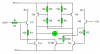
The base emitter junctions are just diodes, the high side transistors are PNP and the low side are NPN.

Connecting the base of the high side to the low side switched both transistors on. The only concern I'd have about the arrangement is the voltage, the base emitter junction will drop at least 0.6V and there are three Vbe drops, e.g. Q3, Q1, and Q6 making a total voltage drop of 1.8V. This won't be a problem when the supply voltage is 3V as the base current will be 25.5mA which should be high enough to give a reasonable saturation voltage. The problem will be is when the battery voltage drops to 2V, it will only leave 0.2V/47 = 4mA of base current so the transistors will go into the linear regions and the motor will turn very slowly. Vbe also has a tendency to rise with the current so the situation will probably worse.

Therefore I conclude that this arrangement is not very good because it will have too shorter battery life so thanks for raising your concern.

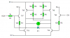
With the arrangement, I posted previously the base current will be high enough even down to 2V. It's not really any more complicated: R3 and R4 are optional and provide extra noise immunity.

**broken link removed**
 
Schematic attached, I've added the shoot through protection but not thebase emitter resistors.

How does the diode provide shoot through protection?
And could you explain your schematic for me? I agree with you in the fact that it doesn't look any more complicated and i could build it without getting any more parts.
 
How does the diode provide shoot through protection?
And could you explain your schematic for me? I agree with you in the fact that it doesn't look any more complicated and i could build it without getting any more parts.

I tell you what, have a go at figuring it out and I'll help you, if you get it wrong.
 
OK this is my guess. Signal from picaxe turns cw high turning on tr8 which then turns on tr4. Turning on tr4 connects r5 to 0v which turns on tr5 making the motor spin and the other side works in the same way. r3 and r4 are just pull up resistors preventing tr5 and tr6 from turning on due to noise. I have no idea how the diode works though but r7 is preventing it from drawing too much current.
 
I'll give you a clue: D1 shorts the base of Tr7 to 0V when Tr4 is on.

Yes R7 does limit the current and is only there to protect the diode.

My design lacks the back-EMF diodes because, at the time of designing it I thought that A 3V motor shouldn't produce enough back EMF to destroy a 45V transistor. I could be wrong, if it doubt, connect a diode in reverse parallel with Tr3 to Tr6 (anode to emitter for NPN and cathode to emitter for PNP).
 
Ahh i see now it shorts the base to 0v and because it is an NPN it requires a high to turn it on and the 1k resistor is just to prevent too much current draw from the chip.
 
The diode shorts the base to the total of Vce (sat) of Tr4 plus the forward voltage of D1. This should be low enough to cut off Tr7.

You do have to be careful, though, and make sure Tr4 is actually saturated when the motor is running. It's also pretty important that D1 is Schottky due to the low voltage that you want to achieve on the base of Tr7.

[edit] Actually I prefer using a transistor as I show below, because it doesn't rely on anything else being well behaved. It can be almost any small signal transistor.
 

Attachments

  • h-bridge  3V 5V...PNG
    h-bridge 3V 5V...PNG
    2.3 KB · Views: 386
Last edited:
I have made one of hero's h bridges up on a piece of strip board and was testing it with a multi meter and across the motor wires i get a resistance of about 800 ohms. from the schematic I reckon I should be getting around 20k. am i correct in thinking this? Oh and i know i'v got a short between 5v and ground. A little mis calculation on where to put the ground wire. Otherwise everything else seems to be OK.
Damian
 

Attachments

  • 847-40039d126826395.png
    847-40039d126826395.png
    2.2 KB · Views: 363
  • untitled..png
    untitled..png
    25.6 KB · Views: 333
  • P1030678..JPG
    P1030678..JPG
    1,013.3 KB · Views: 364
  • P1030677..JPG
    P1030677..JPG
    801.4 KB · Views: 352
You're right, you should get 20k between the motor pins with no power applied (never measure resistance with the power on) and no motor connected. It's possible that the multimeter's test voltage was high enough to allow some current to flow through Tr5's or Tr6's (depending on the polarity) base giving a lower reading than expected.

Have you tested it with the motor and power on yet?
 
No i haven't tested it with power yet as i haven't fixed the short between ground and 5v but i will hopefully fix that today and test it with power and yes i did wounder if the transistor was turning partially on so i tested a spare one i had with the same multimeter and it had a resistance of around 6k.
 
Last edited:
hooked it all up today and the motor tried to go one way but not the other. measured the voltage on the motor wires and i got 2v one way and nothing the other way so i'm not sure what is wrong but something isn't working.
 
Did you connect the inputs to the MCU outputs or did you just test it with pushbutton switches?

I've looked at the circuit again and I don't see anything wrong with it.

Are you sure all the transistors work?
 
I had it all set up on a bread board and was just connecting the wires to 5v or Gnd. All the transistors worked when I breadboarded the other h bridge. I just moved them from the breadboard to the stripboard.
 
Status
Not open for further replies.

Latest threads

New Articles From Microcontroller Tips

Back
Top