terrapinlogo
Member
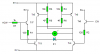
Hi I have designed a mosfet h bridge for a bot i am currently working on from parts i have in my parts bin and was wondering if it would work as i haven't really used fets before and if anyone had any suggestions on how to keep the magic smoke in. I know i probably need some resistors in there but where and what values?
Thanks in advance
Damian
Thanks in advance
Damian
Attachments
Last edited:
")