Continue to Site

Welcome to our site!

Electro Tech is an online community (with over 170,000 members) who enjoy talking about and building electronic circuits, projects and gadgets. To participate you need to register. Registration is free. Click here to register now.

  • Welcome to our site! Electro Tech is an online community (with over 170,000 members) who enjoy talking about and building electronic circuits, projects and gadgets. To participate you need to register. Registration is free. Click here to register now.

MOSFET gets hot and burns

Status
Not open for further replies.

Revibes

New Member
Hello guys please I have a question.

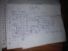
Am making an inverter with SG3525 as the oscillation driver circuit. Now the issue I have is , when ever I turn on the inverter, one channel of the MOSFETs gets hot, while the remaining channel is cool and okay, and before I see the cjhannel with hot heat sink get blown up, please guys what can be the cause of this? Hello guys , you guys requested for the schematics of this my circuit, have included it in the attachment bellow.

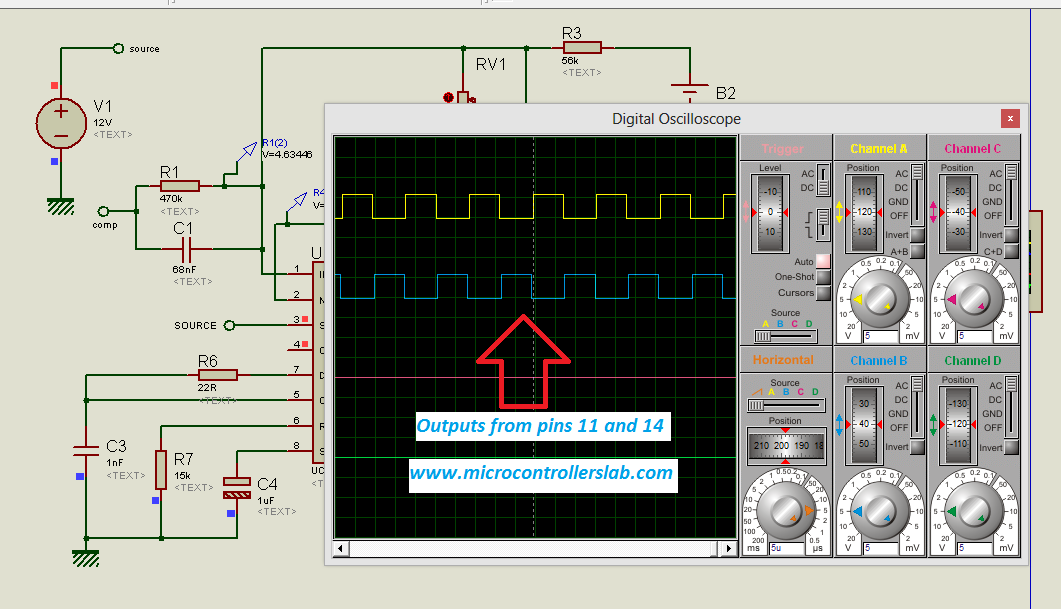
Pin 14 and 11 output reads exactly 5.9v each. And the battery I use as power source is a UPS battery rated 12V 9.0amps
 

Attachments

  • IMG_20220508_072137.jpg
    IMG_20220508_072137.jpg
    1.2 MB · Views: 318
Last edited:
Not enough information. What MOSFETs? What voltages, how is the output coupled to load, etc.?
At the very least, drawn a hand sketch of the schematic and list the devices being used.
 
260N channel MOSFET, I used two .each 1 for each channel. At first the inverter turns on but after some seconds one of the channels gets so hot and burns out
 
260N channel MOSFET, I used two .each 1 for each channel. At first the inverter turns on but after some seconds one of the channels gets so hot and burns out
We still have no idea as to how this is wired. A schematic is required.
There may be a small chance that one of the MOSFETs is blown, needs replacing. Make sure the gate voltage reaches 10V at least, to ensure maximum "turn on" (low RDSon). You may have to put a scope on the gate lines to check voltage levels and pulses
Here is the attachment sir. MOSFETs is 260N channel MOSFETs. UPS Transformer , and also a small battery. Pin 14 and 11 of SG 3525 are both producing 5.9volts. Buy the first MOSFET keeps on getting hot and burns out in some few seconds without load. Why the second MOSFET is ok, not hot at All
 
Here is the attachment sir. MOSFETs is 260N channel MOSFETs. UPS Transformer , and also a small battery. Pin 14 and 11 of SG 3525 are both producing 5.9volts. Buy the first MOSFET keeps on getting hot and burns out in some few seconds without load. Why the second MOSFET is ok, not hot at All
 

Attachments

  • IMG_20220508_072137.jpg
    IMG_20220508_072137.jpg
    1.2 MB · Views: 213
Your 100 ohm Gate R looks a little high.


What does your breadboard look like, picture ....?


Regards, Dana.
 
Doesn't help. Center of transformer is connected to 12V? (battery drawn wrong). And MOSFETS connect each end to Ground? The gate(s) of the MOSFETS are not going positive enough.

My center tap transformer is connected to my batteries vcc +12volts while the source of the MOSFETs Are connected to ground terminal. Is the 100R resistor in the gat not okay? If it is not why is only one MOSFET burning and the other is okay
 
You apply 12V the CT of the transformer?
The Drain of the MOSFETs is at 5.9V? Measured with a meter? No scope?
Do we know if the SG3525 is oscillating?
Is it possible that one FET is on 100% and the other if off 100%?
What is the voltage on the Gates?
 
You apply 12V the CT of the transformer?
The Drain of the MOSFETs is at 5.9V? Measured with a meter? No scope?
Do we know if the SG3525 is oscillating?
Is it possible that one FET is on 100% and the other if off 100%?
What is the voltage on the Gates?
I Applied 12 volts to the center tap of the transformer. It is the output of my oscillation that is 5.9volts and it is connected to the gates of the individual MOSFETs through a 100ohms resistor each. The thing is one MOSFET is getting too hot and burns out in some few seconds while the other one is ok. Why would one of the MOSFETs get hot and burn while the other is okay? As for the oscillation, it is osculating well
 
5.9V on the gate is not enough to fully turn on the MOSFET, you need at least 10V.
The gate resistors could be smaller, perhaps in the 33 ohm range. Also, to be sure, I would put a resistor from gate to ground to ensure a faster gate discharge. The datasheet says the chip can handle the MOSFET gate on its own, but having a 1k or 2k resistor to ground will ensure the gate does not "float" in the range where the RDSon is high.
A similar circuit:
 
Thanks alotsir
5.9V on the gate is not enough to fully turn on the MOSFET, you need at least 10V.
The gate resistors could be smaller, perhaps in the 33 ohm range. Also, to be sure, I would put a resistor from gate to ground to ensure a faster gate discharge. The datasheet says the chip can handle the MOSFET gate on its own, but having a 1k or 2k resistor to ground will ensure the gate does not "float" in the range where the RDSon is high.
A similar circuit:
Thanks a lot Sir, so is it because the gate Voltage not being enough thats why one channel burns out and the other is not hot at all ? If yes, what can be done to increase gate voltage, ? Or should I include a transistor buffer on the output of my oscillation before connecting it to the gate of my MOSFETs? Or any other way to increase it please let me know Sir. Then let's say it has been increased, and I connect like 1k R from gate to source in addition to the buffer transistor or any transistor circuit that would boost up my 5.9 volts to 10volts, will it work?
 
The Drain(s) voltage is 7.1V.
That is a clue. Why is it not higher?
I think we are trouble shooting with a meter not a scope. Is that true?
If we are measuring with a meter, then the Drain voltage should average close to 12V. I don't know what type of meter, or how it is used.
Post pic of breadboard.......
Often, we see mistakes in the breadboard work.
 
The Drain(s) voltage is 7.1V.
That is a clue. Why is it not higher?
I think we are trouble shooting with a meter not a scope. Is that true?
If we are measuring with a meter, then the Drain voltage should average close to 12V. I don't know what type of meter, or how it is used.

Often, we see mistakes in the breadboard work.
Yeah what am using is a metre, I have no oscilloscope. Am using a center tap transformer and each haff end is wind at 7.1v thats y I said each drain voltage is approximately 7.1 but end to end winding is about 12-14V.
 
Status
Not open for further replies.

Latest threads

New Articles From Microcontroller Tips

Back
Top