Continue to Site

Welcome to our site!

Electro Tech is an online community (with over 170,000 members) who enjoy talking about and building electronic circuits, projects and gadgets. To participate you need to register. Registration is free. Click here to register now.

  • Welcome to our site! Electro Tech is an online community (with over 170,000 members) who enjoy talking about and building electronic circuits, projects and gadgets. To participate you need to register. Registration is free. Click here to register now.

Mosfet driver IR2112 help needed

Status
Not open for further replies.

TKS

New Member
Mosfet driver IR2112 help needed (PICS UPDATED)

Hi all,

https://www.ortodoxism.ro/datasheets/irf/ir2112.pdf

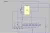
i have this thing in stock, what i want to do is to let it control 6 fets (IRF1104 , N channel) in parrallel (the gate) wich are in the high side configuration.

also the low output needs to control 1 fet (for a bit of regen braking).

Input voltage will be 12/14volts. (car power).

The chip has some pins i have no idea what to do with them.

VSS
VCC
VB
VS

also there are caps / resistors drawn can anyone help me a bit?

with their values or simple explain me where there are for?

In the heigh side configuration we need more gate voltage then suplly voltage right??

Hope you all can help me abit with some values to test it with.

Tks
 
Last edited:
I would take a look at the Application Notes that are provided by I.R. , they are well done and I find them to be very well written and easy to follow.

Start here, http://www.irf.com/technical-info/appnotes.htm

You could also e-mail your local IR representative office, and see if they have any application notes that directly pertain to the IR2112 and/or the design you are trying to achieve. In my past experience, IR are a very helpfull bunch.


The datasheet explains what the pins you listed are used for.

Maybe a little research of a general nature into high-side switching, low-side switching, and motor control involving regenerative braking would explain alot. At the power levels you are considering, there is the potential to destroy alot of components without knowing what went wrong, or the time to prevent it.
 
Yeah the datasheets say names, descriptions but we need to untherstand that names. and i don't do that.

Basicly mosfets is new for me, and i never went to college to learn about programming micro's etc. etc. etc. but i know that with a bit of explanation i can make this.

its not difficult to just build it to the sheme you see on the first page. its just that i need to know the translation of the pins?

Will search for examples altough i hope you can explain a bit the pins..

Tks
 
I think you should at least try to understand the documents instead of following the pictures. As zevon8 said if something goes wrong you won't have a clue how to fix it unless you do some legwork.

VSS is the pin that is conneced to Logic Ground
VCC is a positive supply voltage to which the gate of the lower MOSFET is pulled, called the low side supply
VS is the voltage on the Source of the upper MOSFET, called the high side floating supply return.
VB is voltage which is generated on the chip to drive the gate of a high side N-channel MOSFET to a voltage above VS, called the high side floating supply.

Right there on page 4 of the datasheet, underneath the functional block diagram, is a description of the pins. If you're having this much trouble then I strongly suggest you switch to a simpler project and learn to crawl and walk before trying to do the iron-man tiathalon.
 
Incidentally, IGBT's are crosses between Mosfets and BJT's - typically used for high voltage devices. Personally I've never used them...

So the general idea is that to turn a N-channel mosfet on, you need to put a positive voltage on the gate. Ignoring some of the finer details - the higher the voltage you can put on the gate, the lower the resistance of the mosfet. Obviously check the data sheet for the max gate voltage (Vgs). Exceeding this voltage - typically ~20 - 30V even for a nanosecond will cause the mosfet to fail, usually by short-circuit and lots of smoke. The gate has a capacitance of ~1 - 10nF which is large considering how fast you want it to change between on and off - which is why they make dedicated gate driver chips.

So if you look at the internals of the IR2112, you can see what it does is connect the gate of a mosfet to either a positive voltage or to it's drain - on or off. I assume the lower mosfet is pretty self explanitory - the tricky part is the upper mosfet. If you want the upper mosfet on, you need to connect it's gate to a voltage that is ~12V (or whatever your Mosfet rating) above the load supply - in your case 14+12V. The usual way of doing this is with a "bootstrap" capacitor and diode connected to the switched node - check pg 15 of the design note. One very important thing to keep in mind is that this bootstrap approach will only work if you are PWMing the signal. If the PWM signal ever disappear, or there is some delay on startup, those upper mosfets may suddenly overheat as they turn partially on and dissipate a lot of power.

James
 
Thanxs guys this starts to make sense!

You are right that i need to know to walk before i can make it to run.

But i have build serveral good projects, in fact my locost car is one complete project. suddenly on of them is the reverse and that needs to be electric since the fact that i use a bike engine as powerplant. (no reverse gear).

I wanted to use a startermotor to do the reverse job, i know that they aren't designed for this, but mainly i only need them when they test/aprove my car.

in the UK they just hookup everything an use a simple make button to fly backwards.. i thought that would be allot more abuse for the motor than PWMing 6 mosfets from a HWPWM micro. In my setup i need to look at the type of motor i have (series wounded rotor and stator i guess) because of the regen braking future, i mean to say to be able to cope with the voltage generated when the motor is turning when no PWM signal.

I had 2 things in mind:
- another MOSFET shorts both motor leads?
- a diode after the upper mosfet to mosfet supply (=Vdd) (think its this one)
- a diode after the upper mosfet to ground (in blocking position) doesn't make sense????

The lower mosfet won't be there in my design because i cant see a reason to fit it? in fact i use this chip only to create the High gate voltage and to transform the 5volts pwm signal to mosfet gate signal..

Ok, this said i only have 2 question/doubt left.

I see that between Vdd and Vss is a cap this is there for only smooting out purposes right?? i will fit a 1uF there.

Then the diode i guess a 1amp 0,6volts 1N4001 should do the job. (its rated for my voltage).

then comes the last part the cap wich generates for me the bootstrap (higher then supply voltage) wich value should i take for that? my feeling says 1uF should do the job since there is basicly no difference between supply voltage and controllig voltage.

Comments please?

Tks

p.d. gonna open up the motor to see if i need to care about regen/breaking/ that i have a type of motor wich creates voltage when its turned freely..
 
Well its series wounded

i have 1 connection to positive and ground is case.

It series wounded because i have opened it up and there are no magnets just coils..

Do i need regenbreaking?? / Feuture to minimize generator effect??

Tks
 
I think you will find that regenerative braking is not simply shorting the motor with a FET. Maybe a small toy motor, but a motor of any size is going to detonate your FETs. It can only end in tears.

You need a fairly decent sized resistor to dissipate the heat. It will all depend on the time required to stop the motor, the rate at which it is going to be stopped, etc.

Perfect example, many subway systems use series/parallel configured DC motors, series to get moving, parallel for speed. The braking is handled in a similar way, progressive increase in the resistive load. Braking is regenerative, with many banks of spiral wound metal resistors the size of your forearm. They look like heating coils, and essentially become that. The heat generated is used for heating the train cabin in winter. Even in industrial settings where motors use regenerative breaking, the resistors are big.
 
One thing to note about series wound DC motors... they cannot control their own speed. If for whatever reason there is no load, or it gets disconnected accidentally or otherwise, they can, and often will, accelerate until they destroy themselves. This can happen very quickly by the way, and is generally not enjoyed by anyone.
 
Typically the caps are ceramic and placed as close to the chip as possible. The 1N1004 should be okay for the bootstrap.

I'm not sure if the bootstrap approach will work without the lower mosfet. You should test it out by attaching a meter on the bootstrap voltage and just running a small DC motor to see if it stays above the rail voltage. I think if the motor back-emf approaches the rail voltage, the bootstrap voltage will decrease to just a little bit over the rail voltage.

Putting in reverse biased "freewheeling" diodes is a reasonable idea in any case - the motor will spark, and it's reasonable to shunt them away from the motor. The diodes should be rated for the max expected motor current (but for short durations). The idea is that if you have schottky's with lower Vf's, they'll end up dissipating that extra power instead of heating up the mosfets even more.

The other thing to be aware of is that if this thing gets pushed or goes down a big enough hill, the motor may start generating enough power to exceed 12V, in which case, the freewheeling diodes/parasitic diodes in the mosfets will cause the supply rail to rise above what you'd expect. I think the usual thing is to have another mosfet and a resistor bank setup to dissipate the extra power on the supply rail in order to keep it from blowing out all the parts.

James
 
Mhh ok,

well its a reverse, sow i never will go down hill backward.. and if i do it i apply brake or i select neutral. Sow in fact i need minimal regen / brake / generator feauters in this application on this controller.

Do i need to put the diodes from motor feed to Motor supply (in fact like the mosfets ones are)??

Or do i need to put them accros the motor terminals (in fact from motor feed to ground in blocking direction)

Also did my idea for the caps values seem reasonable?

Wil drawup a sheme when i can.

Tks
 
Ok,
I'm designing the scheme with the Free LT spice program.

I was thinking isn't it easyer to convert 14volts to 10+14 = 24volts????
shouldn't that do the job instead of the bootstrap?

Tks
 
Scheme

Well hope that someone comes up with a good idea or with a easyer alternative to be able to hook it up!
 

Attachments

  • IR2112StarterScheme.JPG
    IR2112StarterScheme.JPG
    31.9 KB · Views: 1,417
What do i do? Any help maybe possible guys?? opinions??
if someone knows a better way of pulsing the six mosfets...

come on you guys only need 5min to show up a better possibility..

Tks
 
The decoupling/boost caps look reasonably sized. If you want to supply an external bootstrap voltage, just plug it into Vb, and reconnect the 1uF between Vb and ground so it can decouple the 2-3A current spike that will happen when the mosfets turn on.

If you do decide to just keep the diode/cap bootstrap configuration, just read through what I wrote before about not having the lower mosfet. It may work sufficiently well with out it for your configuration, but you'll need to test it out.

I can't make out the diode ratings, but they're in the right direction. You should also clamp it to ground as well - hypothetical question: what happens when the motor terminal spikes down to -20V with the gate being held at ground?

If you go through the data sheet and app notes, the only other thing might be to put 6x ~100 ohm in series with each of the mosfet gates to prevent some high frequency oscillations. Otherwise, using the gate driver chip is about as easy as it is going to get.

James
 
Ok, sow in fact i could better eliminate the diodes and fit 1 mosfet?

problem is that i need/don´t want overlapping of the mosfets because then the lower one will be burned out quet easy....not?

Will fit 2 to ground and 2 to vdd if they blow i will fit more??

they are huge! will try to add as much of them as i can.

the gate part i don´t untherstand what would you do? thats in fact what i need to know...

Tks
 
TKS said:
Ok, sow in fact i could better eliminate the diodes and fit 1 mosfet?

problem is that i need/don´t want overlapping of the mosfets because then the lower one will be burned out quet easy....not?
Correct, if the circuit tries to brake with the motor spinning at a good clip, it could burn out - but I'm also saying that without a mosfet there, the upper mosfets may not turn on fully when you approach no-load speeds. If the motor is always moving relatively slowly (back-EMF is low), the circuit should be okay as long as the PWM signal is present.

TKS said:
Will fit 2 to ground and 2 to vdd if they blow i will fit more??

they are huge! will try to add as much of them as i can.
Are you talking about the diodes?
They need to be sized so that they can handle the voltage spikes that happen when the mosfets switch. The average current they need to handle is relatively small. A "1 Amp diode" might have an instantaneous current rating of 3-5 Amps, so read the data sheets.

TKS said:
the gate part i don´t untherstand what would you do? thats in fact what i need to know...
Ahh, don't worry about it. It's something you do when people complain about radio interference or mysterious part failures - look at the app notes for details. Lots of engineering time goes into writing those things, and they are very useful.

James
 
Ok, i wanted to fit 4 3amp (rated) diodes.. but if i hear you than i should be done with 2 of each in both direction right??

Can i eliminate the resistance of 10R?? i don't have a 10R with significant wattage...

guess its 1/4 or less.. :(

Tks

p.d. the circuit should be able to do a full motor start with load on it.. i don't have a overamp limit built in because of the reason that fitting resistor in the feeding line with a starter as consuming doesn't look wise... also because i will limit the max rpm/amps with the max pwm the controller feeds...

anyways 6fets of my size should give me 600amps continous and 2400ams pulses sow i gues it should be quit bullet proof also i hope that the amd cpu cooler will let the lot stay cool.

is it a trick if i fit a 27volt zener from the motor to the 1uF cap??

it would need to stay open when the cap doesn't has de 27volts on it...

sow in fact i though of charging the cap with the back emf of the motor?????
maybe a diode to prevent to blow the chip? before the pin?

as you can see i try to do my best on this

Thanxs already for your help!
 
Last edited:
The diodes i use are the 1N5401 they have 3amps continous and :
Peak forward surge current 8.3ms single half sine-wave superimposed on rated load (JEDEC METHOD) at Tl=105degrees = 200Amps

have 2 of them in parallel sow i gues we have finished that stage...

wel i'm gonna hook up the caps and tomorrow test it..

a small motor i don't have one, only a bike starter instead of a car starter..
(dunno wich is worse) think i start with a bulb a couple of amps...

wich frequency would be the safest to start with? the lower the better right?? regarding to mosfet in non fully conduct fase..??

Regards,

Tks
 
Status
Not open for further replies.

Latest threads

New Articles From Microcontroller Tips

Back
Top