okay, where to start...
The diodes should be more than sufficient.
Can i eliminate the resistance of 10R?? i don't have a 10R with significant wattage...
Mosfets have capacitve gates - there is only current going through that resistor when the mosfet turns on and off, otherwise there is no current going through them, and I'd expect acual power dissipation in them to be in the milli - microwatt range.
anyways 6fets of my size should give me 600amps continous and 2400ams pulses sow i gues it should be quit bullet proof also i hope that the amd cpu cooler will let the lot stay cool.
Considering "0000" copper wire (i.e. 1/2 inch or 13mm copper rod) is rated for 400amps, and I don't see any of that, I'd expect the realistic rating is a bit lower...
sow in fact i though of charging the cap with the back emf of the motor?????
maybe a diode to prevent to blow the chip? before the pin?
? the back emf from the motor won't cause the voltage on the capacitor to increase (by much). If the motor is being forced to turn externally, then you'll need to worry about over-voltage.
I'm now realising that the only reason for me to use this chip is that its for purposes of positive feed to the N channel Fet..
If you mean: "The only reason to use this chip is to drive a high-side FET", then yes, that would be it (and a good reason as well). You can find less capable chips, and might be able to save ~20% of the cost of the chip or something.
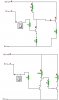
i was studing the datasheet and i saw that COM = low side return, the above pic its just ground..(page 1)
watching at VCC its Low side supply is it true that bove are for me ground?? how the hell that cap can then charge it self??
This chip has two *different* sections. One side is built to drive a low-side mosfet, the other side can drive a high-side mosfet. The low-side mosfet is easy to drive and doesn't need the bootstrap capacitor or diode. The high-side on the other hand -
The idea is that when the high-side mosfet is off, the motor terminal will be at ground. At this time, the capacitor will have 11.4V across it (because of the bootstrap diode). When the high-side mosfet turns on, the motor terminal will be at 12V, the capacitor will *still* have 11.4V across it, and the upper capacitor terminal will be at 12+11.4=23.4V, which is enough to turn the mosfet fully on.
James
 sow in fact an 1,5Watt 21ohm resistor