Continue to Site

Welcome to our site!

Electro Tech is an online community (with over 170,000 members) who enjoy talking about and building electronic circuits, projects and gadgets. To participate you need to register. Registration is free. Click here to register now.

  • Welcome to our site! Electro Tech is an online community (with over 170,000 members) who enjoy talking about and building electronic circuits, projects and gadgets. To participate you need to register. Registration is free. Click here to register now.

Monitoring car battery strength using Schmitt Trigger circuit

Status
Not open for further replies.

Lim Wai Khang

New Member
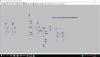
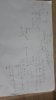
Hi, i am new in analog designs. Now, i am trying to design a circuit using STC(Schmitt Trigger Comparator) circuit to monitor the voltage level of a car battery which normally is around 12 volts. Im trying to use two LEDs,green and red, to indicate the voltage level of the car battery. If the voltage is above 11.6v the green LED will light up, then if voltage is below 9.6v, the red LED will light up. This means that the upper threshold voltage is 11.6v and the lower threshold voltage is 9.6v . Im currently stuck with this circuit , but I was advised to use zener diode and to scale down the UTP and LTP voltage.How can i do that??
 

Attachments

  • Circuit.png
    Circuit.png
    102.3 KB · Views: 261
When I look at your circuit the resolution is low and I can not see some pieces. It looks like you used screen capture to grab picture of your entire monitor. You can use paint or some program to crop the picture where only the interesting parts are posted. Or you can send the spice file.
 
The inputs of some LM358 opamps do not work if they are within 1.5V from the positive supply. Yours are very close, reduce Vref to about 5V or 6V.
Vref should be a regulated voltage, use a voltage reference IC or a Zener diode.

Your 50k resistor should be a voltage divider to reduce the battery voltage down to near Vref.
The 100k hysteresis resistor should have a much higher value.

I tried to simulate your circuit with LTspice and saw the switching happened at about 13.3V but the LTspice program crashed. The slow LM358 took about 0.5ms to switch.
 
I think you want 3 states. RED LED, Green LED and no LED. Where you are going this can not happen with out more parts.

First your circuit can only make one LED come on. I changed the way the LEDs are wired up.
Next I used R3, R5 to divide Vbat down to about 1/2. (near 6 volts)
I added D3 to make a good Vref.
I used only one supply V2 so it is more like what you will do in a car.
I do not have the op-amp you do so I just picked on at random. Could be really wrong.
1538491832337.png

For simulation I made a battery V2 ramp from 9V to 13V so you can see what is happening.
1538491962121.png

I know this is not what you want but it is a start.
 

Attachments

  • Battery LED Ron.asc
    1.8 KB · Views: 202
The LM3914 IC is not made in a DIP package anymore. TheLM3914 is surface mount now and the LM3915 and LM3916 are not made anymore..
 
I think you want 3 states. RED LED, Green LED and no LED. Where you are going this can not happen with out more parts.

First your circuit can only make one LED come on. I changed the way the LEDs are wired up.
Next I used R3, R5 to divide Vbat down to about 1/2. (near 6 volts)
I added D3 to make a good Vref.
I used only one supply V2 so it is more like what you will do in a car.
I do not have the op-amp you do so I just picked on at random. Could be really wrong.
View attachment 114693
For simulation I made a battery V2 ramp from 9V to 13V so you can see what is happening.
View attachment 114694
I know this is not what you want but it is a start.

What if i want to use two supplies instead of one? will it be more stable?
 
What if i want to use two supplies instead of one? will it be more stable?
D3 is a regulated voltage reference called a Zener diode. Then a second supply is not needed.
The old KDZ6.2 is not recommended for new designs so select a newer Zener diode that is from 6.2V to 6.8V.
 
So this is the circuit now but im not sure why the Vout of the circuit is not a square wave. I tried scaling the voltage by the ratio of 2.1
 

Attachments

  • Batt LED.asc
    2.1 KB · Views: 205
  • Scale.jpg
    Scale.jpg
    26.2 KB · Views: 230
Try these values :
R2=100k, R3=removed, R5=10k, R7=10k.
 
So now, i got the circuit to work as intended but, my upper threshold voltage is somewhat accurate and my lower threshold voltage differs.
Are there any ways to fix this?? i should get around UTP=11.6v and LTP=9.6v.
 

Attachments

  • wave ltp.PNG
    wave ltp.PNG
    82 KB · Views: 219
  • wave utp.PNG
    wave utp.PNG
    78.4 KB · Views: 236
  • wave.PNG
    wave.PNG
    55.1 KB · Views: 222
  • Batt LED.asc
    2.2 KB · Views: 189
Status
Not open for further replies.

Latest threads

New Articles From Microcontroller Tips

Back
Top