Continue to Site

Welcome to our site!

Electro Tech is an online community (with over 170,000 members) who enjoy talking about and building electronic circuits, projects and gadgets. To participate you need to register. Registration is free. Click here to register now.

  • Welcome to our site! Electro Tech is an online community (with over 170,000 members) who enjoy talking about and building electronic circuits, projects and gadgets. To participate you need to register. Registration is free. Click here to register now.

Momentary button triggered 2 bit binary counter?

Status
Not open for further replies.

turningjapanese

New Member
Hi all,

I am trying to come up with a circuit to manually control my automatic gearbox on a 4x4.

The gearbox has two solenoids to select the gear. I shall refer to them as S1 and S2.

In 1st gear S1=on S2=off
2nd gear S1=on S2=on
3rd gear S1=off S2=on
4th gear S1=off S2=off

i understand the order is decimal 2,3,1,0

(or if we swap S1 and S2 over 1,3,2,0)


i have identified this as a kind of 2 bit binary counting.

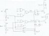
What i am looking for is a simple circuit which has 2 momentary switch inputs, one to count up, and one to count down. The circuit also needs 2 relay outputs which i can then use to control the solenoids.

In an ideal world a seven segment display showing the gear would be brilliant.

I understand this is easy to achieve with a PIC but i have very limited programming experience and no equipment for this, i do however have a basic grasp of electronics.

Any help would be much apreciated

Thanks in Advance

Stacy G Johnson
 
Last edited:
Just trying to understand your requirements ....

You have four states:
1 0
1 1
0 1
0 0

You want to be able to transition up/down between adjacent states by using one or two momentary switches.

Each state should be able to energize a relay coil, according to its designated values.

Is this the basic idea?
 
That's why they invented microcontrollers.

Logic chips are ok for very standard signal processing but when you have a special requirement such as yours, a micro is the only answer.
You can do it with logic gates but you don’t want to go from 4th gear to first if you push the up button once more!
 
It's not the only answer, but it's sure the easier of the two.
 
Or just use some simple logic - up/down counter chips are very common, as are logic ones. See attached schematic.

If you are using CMOS logic, then the AND (could be NAND if you wanted) gate at the bottom needs a pullup resistor (10k is fine) on each input.

You might also need debouncing capacitors across the switches so that you don't jump multiple gears in a single press.

The gear is displayed on a 7-seg common-anode LED display.

Also, you might find that the "UP" switch goes down and the "DOWN" goes up - just swap the labels.
 

Attachments

  • gears.gif
    gears.gif
    28.2 KB · Views: 452
Last edited:
It's no good suggesting a simple circuit like the one above, unless it is complete.
What "stops" have you got on the buttons to prevent them cycling?
How are you going to decode the lines to operate the solenoids?
(I don't think the correct gates have been shown.) You also need to show some pull-up resistors.
However the basis of the circuit seems to workable if the fine details can be implemented.
 
Last edited:
Opps, I think I was counting backwards. collin55, do you think this one will work? I think it will.
 

Attachments

  • gears.gif
    gears.gif
    29.3 KB · Views: 293
The up button will work but I don't think the down button will work.
When the counter is at zero, the two outputs are 0 and 0 and the down button is seeing 1 and 1 How does it advance the count?
 
Last edited:
Right. The "D" symbol is AND, a triangle is a buffer, a circle on input or output is an inverter, a curved "D" (curved line at input) is an OR (not used in above circuit), a curvy "D" with an extra curve at the input side is an XOR. I think they're the american standard symbols(?)

See Logic gate - Wikipedia, the free encyclopedia
 
Last edited:
The up button will work but I don't think the down button will work.
When the counter is at zero, the two outputs are 0 and 0 and the down button is seeing 1 and 1. How does it advance the count?
 
Last edited:
Umm... why are you decreasing the count below 0? I think you'll find that the UP button doesn't work when you reach the top (i.e. b'11) either. This stops you from going from 4th gear to 1st gear, or from 1st to 4th (i.e. stops the wrap around).

As an aside, the down button doesn't advance the count, it decreases it. The UP button is for increasing the count.
 
You are right. I wan't thinking.

When the up/down counter first turns on it will be 0 0. How are you going to deal with this?
 
Last edited:
Tranny UP/Down

Here is my solution: I haven't played with State Transition Tables, and Venn diagrams for maybe 20 years, but it is sorta like riding a bicycle...

My implementation prevents wrap around, and requires no output decoding because the two state variables S1 and S2 drive the solenoids directly.

You can build it with a dual D Flip-Flop (HC74) and 2ea quad 2 input Nands (HC00).

Vdd on the schematic is a cleaned-up (bypassed) version of the 12V power bus which also powers the chips.
 

Attachments

  • StateTable.jpg
    StateTable.jpg
    69 KB · Views: 320
  • StateTable1.jpg
    StateTable1.jpg
    49 KB · Views: 327
Neat solution MikeMI! I see a couple of small oversights (I didn't check the logic):
- the 4k7 resistors will need diodes in series otherwise the voltage on flip flop clock will only reach 1/2 rail (cmos switches at 1/3 & 2/3 rail); a discharge resistor is then needed across the capacitor.
- The HC series doesn't like being run from 12V, 5V (nom) is recommended, 7V is abs max. 4000 series runs up to 16V though.
 
I can't get the solenoids to produce the correct pattern.

Equations were ok. Small bug in hand-drawn schematic. See the LTSpice simulation attached here. The zip file contains all files required to run the simulation. I also added a 5V regulator to run the logic, and cleaned up the clock generation. Note that the flops are positive edge triggered, so the rising clock edge is delayed from the button push to meet the setup time of flops.

I assumed that both switches would never be pressed simultaneously, which greatly simplifies the gating. If this is a problem, you could add terms to prevent that from changing S1 or S2. I would use a momentary spring-return center-off switch for the Up/Down switch. That effectively locks out the possibility that both are pressed simultaneously.

Not shown is a power-up reset to initialize S1 and S1 to First gear. That could be done using the async. set/clear inputs to the flops.
 

Attachments

  • TrannySchem.jpg
    TrannySchem.jpg
    85.4 KB · Views: 530
  • TrannyTraces.jpg
    TrannyTraces.jpg
    112.9 KB · Views: 278
  • Tranny.zip
    157.6 KB · Views: 169
Status
Not open for further replies.

Latest threads

New Articles From Microcontroller Tips

Back
Top