Continue to Site

Welcome to our site!

Electro Tech is an online community (with over 170,000 members) who enjoy talking about and building electronic circuits, projects and gadgets. To participate you need to register. Registration is free. Click here to register now.

  • Welcome to our site! Electro Tech is an online community (with over 170,000 members) who enjoy talking about and building electronic circuits, projects and gadgets. To participate you need to register. Registration is free. Click here to register now.

Moisture Circuit to Arduino to Transmitter

Status
Not open for further replies.

ibwev

Member
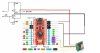
I have assembled an Arduino 5V Pro Micro https://cdn.sparkfun.com/datasheets/Dev/Arduino/Boards/ProMicro16MHzv1.pdf connected to a 433 MHz RF Transmitter connected to a moisture circuit (see picture). I am trying to send an RF transmission once the moisture circuit senses moisture. The indicator LED on the Aduino and the LED on the moisture circuit both light when moisture is sensed; however, the light fades in and out. I am sure I need steady power to the Aduino for it to function properly. How should the circuit be altered to supply a steady flow of current to the Aduino when moisture is sensed?
 

Attachments

  • AduinoTransmitterMoistureCircuitTroubleshoot.jpg
    AduinoTransmitterMoistureCircuitTroubleshoot.jpg
    123.9 KB · Views: 139
... the light fades in and out...
Which light?

What is the normal voltage at the "RAW" terminal (I'm assuming ≈9VDC), and what is it when the moisture is sensed?

What is the purpose of the ckt to the left of the battery?
 
Which light?
The LED on the moisture circuit and the LED on the Pro Micro.

What is the normal voltage at the "RAW" terminal (I'm assuming ≈9VDC)

The Pro Micro can operate between 6V and 16V. Currently, I am using 9 volts on the circuit. I intend to run it on 12 volts to give the transmitter maximum range.

what is it when the moisture is sensed?

I have seen it anywhere between 2 volts and 8 volts. The voltage appears to depend on how much moisture is sensed. The more wet the source the higher the voltage.

What is the purpose of the ckt to the left of the battery?
What is the "ckt"? There is an LED to the left of the battery. Its purpose is just to verify the circuit is working.
 
I noticed that the Arduino ground is not connected to the battery ground. And what are the to left facing arrows? Can you share the sketch?
 
I noticed that the Arduino ground is not connected to the battery ground.
If I connect the Aduino ground to the battery ground then the transistor won't be able to serve as a switch when moisture is detected. I am trying to send power to the Aduino only when moisture is detected. Perhaps there is a better way to switch power to the Aduino.

And what are the to left facing arrows?
The left facing arrows serve as probes that sense moisture.
 
What is the "ckt"? There is an LED to the left of the battery. Its purpose is just to verify the circuit is working.
My apologies for using the abbreviation "ckt": it stands for the word "circuit".

Where did this circuit:
upload_2017-2-4_16-15-45.png

come from?

It would appear that you're attempting to use it as a switch to connect the ground legs of the Arduino and the Xmitter (through the transistor), thereby turning them "ON".

Is that correct? If so, varying conductivity will hugely affect the performance of the transistor as a switch (more like a volume control). This will result in the symptoms you are observing.

There are better ways to do this.
 
Last edited:
My apologies for using the abbreviation "ckt": it stands for the word "circuit".

Where did this circuit:
View attachment 104087
come from?

I'll be ready for "ckt" next time. The moisture part of the circuit came from https://www.instructables.com/id/Simple-Water-Sensor/step4/Build-It/.

It would appear that you're attempting to use it as a switch to connect the ground legs of the Arduino and the Xmitter (through the transistor), thereby turning them "ON".

Is that correct?
That is exactly what I am trying to do.

There are better ways to do this.
Please help me learn how to do this a better way.
 
EDIT EDIT EDIT
upload_2017-2-4_20-5-20.png

This circuit will feed the RAW pin of the Arduino - a better method of control when using an NPN transistor as a switch.

You might have to play with the value of R1. Don't forget that the conductivity of the "moisture" will greatly affect the performance of the transistor "switch".

And there is no real need for R3 and the LED, since the Arduino already has an "ON" LED.
 
Last edited:
I understand what you are trying to do in the post #1 circuit (switching the ground), and it might work. But, like the circuit in post #8, the turn on and turn off will be gradual as the moist soil resistance crosses a threshold value. A single transistor, no matter how high its gain, still has a large linear active region, and the circuit in post #8 has a gain of 1 so it has a slower transfer curve than your original circuit.

To get the snappy full-on/full off action that will provide crisp power changes to the arduino, you will need at least one more transistor and some positive feedback. The circuit is called a Schmitt Trigger, can be done with discrete transistors or an opamp or a comparator or a digital logic IC, and there are lotsa example schematics on the innergoogle. Read up on them, and we can get the action you want.

ak
 
Last edited:
Thank you cowboybob and AnalogKid.

I have assembled the circuit in post #8 using a transistor http://www.nteinc.com/specs/100to199/pdf/nte123ap.pdf I had on hand. Some of the time, it works. I don't know enough about circuitry to know how to interpret the datasheet of the transistor. Somehow, I am loosing voltage between the base and the emitter when the collector is receiving voltage between 2 and 8 volts. If you know of a "Transistors for Dummies" tutorial, please recommend it so that I may better understand the datasheet.

To get the snappy full-on/full off action that will provide crisp power changes to the arduino, you will need at least one more transistor and some positive feedback. The circuit is called a Schmitt Trigger, can be done with discrete transistors or an opamp or a comparator or a digital logic IC, and there are lotsa example schematics on the innergoogle. Read up on them, and we can get the action you want.

I have done some reading on the Schmitt Trigger. How do I calculate, or find out, the required resistor sizes for this circuit? I have looked at Google images for Schmitt Trigger and I can't seem to find a 12 volt Schmitt Trigger example.

EDIT EDIT EDIT*******************************************
Hold everything.

I just found out that the ProMicro has an ADC converter. For my skill level, it may be easier to to send an analog signal of up to 5 volts to a ProMicro ADC pin. How can I safely reduce the voltage coming from the moisture probes into the ProMicro so that it does not exceed 5 volts? Is it as simple as putting a resistor between the 12 volt moisture probe and the ProMicro?

EDIT 2**********************************************************
I think I found the answer. http://www.learningaboutelectronics.com/Articles/How-to-reduce-voltage-with-resistors.php
 
Last edited:
... Hold everything. ...
A wise decision, at this point.

ibwev, you're sort of wandering all over the place with this thread.

Your initial schematic indicated that you were looking for a circuit that would respond to the presence of "moisture" and "turn ON" (i.e., supply power to) your ProMicro AND a 433 MHz RF Transmitter assembly.

Your description of how that circuit was working confirmed that conclusion. Only now, you appear to want to change that design such that the moisture probe is simply going to be attached to an an ADC input of an already powered up ProMicro (AND the transmitter as well, apparently) and then trigger, by way of software, some event.

Two entirely different circuit requirements. Which is correct?

It would be very useful to know just exactly what is the composition (as best as you can describe it) of the, 1. "moisture" you speak of, and 2. your "moisture" probe?

This would give us, at the least, some idea of what electrical characteristics we could expect when proposing any circuit ideas.
 
It would be very useful to know just exactly what is the composition (as best as you can describe it) of the, 1. "moisture" you speak of, and 2. your "moisture" probe?

I apologise for my ignorance of circuitry causing confusion. Thank you for your patience.

The moisture probe is simply a pair of wires and the moisture I would like to detect is standing water caused from condensation.

I thought it might be easier for the ProMicro to detect the analog signal from the probes and then the ProMicro turn the RF Transmitter on. I now realize that the ProMicro can not supply enough voltage to adequately supply the transmitter.

My goal is to send a transmission when condensation is detected by the pair of wire probes.
 
Is the arduino modulating the transmitter with a data pattern or message? If not, you can key the transmitter on and off with one 2N7002 transistor and a couple of resistors.

ak
 
The moisture probe is simply a pair of wires and the moisture I would like to detect is standing water caused from condensation.
Condensate is notorious for very poor and variable conduction. If I might suggest, is there an adequate volume of fluid to allow you to use a float switch (like for a boat)? That would really simplify the circuit.
 
is there an adequate volume of fluid to allow you to use a float switch (like for a boat)?
There is not an adequate volume of fluid to allow a float switch.

Condensate is notorious for very poor and variable conduction.
Is it reasonable for the ProMicro to send a pin high to cycle the transmitter if the ADC pin receives any voltage above a certain threshold. Is there a component similar to a contactor that might can toggle the power to the transmitter? (see pic)
AduinoTransmitterMoistureCircuitTroubleshoot2.jpg
 
POST ISSUE 11 of 2017_02_09

Hi IBW,

Below is a circuit for you to consider.

spec

2017_02_08_ISS2_ETO_MOISTURE_SENSOR_SWITCH_V1.png

ERRATA
(1)

CIRCUIT DESCRIPTION

(1) The circuit uses no microcontroller, although a microcontroller can be switched on in addition to the RF transmitter.
(2) If no moisture is detected, the PMOSFET is turned of and the circuit consumes only a few micro amps.
(3) When moisture is detected the PMOSFET is turned on for 100 mili seconds and off 1 second (to save power).
(4) The on period is set by R7/C1.
(5) The off period is set by R6/C1.


NOTES
(1) The timing capacitor C1 is a metal film type.
(2) Unless otherwise stated all capacitors are ceramic X7R dielectric +-10% or tighter, 25V or higher.
(3) R5 is nominal and may need to be adjusted to suit the characteristics of the moisture sensor.
(4) The 555 timer is a CMOS type for low current consumption and enhanced performance
(5) All resistors are metal film, 250 miliwatts or higher, +-5% or tighter.

VENDORS
(1) https://www.digikey.co.uk/products/en/capacitors/film-capacitors/62?k=capacitor+film&k=&pkeyword=capacitor+film&pv7=197&pv1989=0&pv13=1529&pv1293=20&pv1293=54&pv1293=31&pv1293=37&pv1293=42&pv1293=45&pv1293=3&pv1293=12&pv1293=17&pv1293=19&pv1293=23&pv1293=137&pv1293=134&pv1293=25&FV=fff40002,fff80010&mnonly=0&newproducts=0&ColumnSort=0&page=1&stock=1&quantity=0&ptm=0&fid=0&pageSize=25

DATASHHETS
 

Attachments

  • KEM_F3101_R82.pdf
    1.3 MB · Views: 156
  • TI_LMC555_CMOS_version$.pdf
    1.2 MB · Views: 132
  • Vish_Si2371EDS_PM_30V_4.8A_80mR_12VGS_1.5VGT_SOT-23_$$.pdf
    217 KB · Views: 121
  • Fair_BC546-BC550_NBJT.pdf
    191.9 KB · Views: 125
Last edited:
Is there a component similar to a contactor that might can toggle the power to the transmitter?
1. In your first post you had the sensor transistor switching power to both the arduino and the transmitter.

2. In post #16 the arduino is powered constantly, the sensor transistor sends a trigger signal to the arduino, and the arduino switches power to the transmitter.

Either way will work, but having the arduino powered all the time will run down the batteries much more quickly. Which way do prefer?

ak
 
Here is an update to your schematic in post #1. It adds a 2nd transistor for better switching action. This circuit draws about 20 uA when dry, so the battery life should be pretty good.

ak
Moisture-1-c.gif
 

Attachments

  • Moisture-1-c.pdf
    9.4 KB · Views: 140
Last edited:
Let's go back to your original circuit and add a simple modification (the components in RED):
upload_2017-2-8_11-6-15.png

I simmed the original circuit (from Post#1), using resistors of various values(up to 0.5MΩ) as substitutes for varying conductivity, and the original circuit (somewhat to my surprise) worked quite well. The circuit was most sensitive near the "0" position on the 50k pot device above.

The 433mHz xmitter only draws about 40mA but I have no idea what the ProMicro draws. Not sure why LED1 is needed. Just seems like wasted power since the ProMicro has an LED. If removed, replace R2 with a 4.7k resistor.

The life of the 9VDC battery is unknown for this circuit.
 
Last edited:
Status
Not open for further replies.

Latest threads

New Articles From Microcontroller Tips

Back
Top