Electro Tech is an online community (with over 170,000 members) who enjoy talking about and building electronic circuits, projects and gadgets. To participate you need to register. Registration is free. Click here to register now.
Welcome to our site! Electro Tech is an online community (with over 170,000 members) who enjoy talking about and building electronic circuits, projects and gadgets. To participate you need to register. Registration is free. Click here to register now.
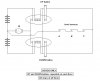
This is what I managed
I intend LR to mean latching relay, or a relay that latches the button press.
I don't even know if it will work.
It is pretty messy as i don't have a scanner.
After drawing and discarding many attempts,
i have come up with this.
Its only an outline, it needs some additional work.
Maybe opening contacts at the upper and lower points
to prevent the 'UP' relay being engaged with the unit at the top.
And similar at the bottom,
to prevent the 'DOWN' relay being engaged with the unit at the bottom.
Also i dont like the two N.O. contacts across the supply, i would
like to put in extra contacts to reduce the likelihood of shorting.
Or rearrange the circuitry.
However, it looks workable, but only as a 'Goods' type unit.
Making it miss out floors, and including buttons in the lift
starts getting very complicated.
That is a pretty good diagram, but it doesn't really suit my needs. I just do not know about how I can add buttons for floors. I am on the verge of giving up. If anybody really wants to help, PLEASE post a real circuit diagram I can use. By the way, can i just be told about how i need to wire the flip flops circuit? I'll do the rest.
Thank you for your appreciation, it took me three days.
And i realise it does not meet what you want, i put it forward as a possible basis for including extra circuitry.
You may not need flip-flops, you may only need bi-stables - which are easier to drive.
I assume that you would want them as 'memories' or just 'flags'.
A short 'wait' period would also be needed i think, so that the lift can then respond,
to a call from another floor, after completing the call in progress.
The arrangement i posted (# 45) uses simple 'make' press buttons for UP and DOWN,
these can be paralleled up and extended to the other floors. The thing i could not see an easy way to perform, is the operation of 'going past a floor' to answer a call more than one floor away. There might be an easy way to do this, but i havent seen it yet.
If you can see a way to do that, then i think that will meet your request.
With only three floors, such a call can only come from the top or the bottom.
It might be possible to include two relays specifically for those two eventualities.
The arrangement 'as-shown' is extendable over as many floors as you like, but as said- it would stop at each level.
It would no longer be extendable in that way if such special purpose relays were included for the middle floor of a three floor set-up.
I dont really see adding buttons for each floor as a problem.
******************
I have tried to see an arrangement using relays, because they are easier to understand for many people, but i cant see an easy way to meet your spec.
I think that your best way would be to sort out a micro-processor driving a motor, and fix up three sensors to drive the micro-processor.
Then ask nicely for someone to help with programming it.
Or maybe such small programs are aready downloadable from somewhere.
Given your limited time, and limited experience, i really think this is your most likely route to success.
Fixing up a small microprocessor and giving it a program to run from press buttons to call the lift, and sensors in the lift shaft is something that can be done in the time available.
I would be interested to hear from others, whether or not they agree with this approach.
I thank you for your efforts, but this is just not what we want. I need a circuit that can take it to any of the called floors. How were they made long ago anyway?
I am still looking for help. Please post a circuit diagram which I can use.
I thank you for your efforts, but this is just not what we want. I need a circuit that can take it to any of the called floors. How were they made long ago anyway?
I am still looking for help. Please post a circuit diagram which I can use.
Hi,
I've come up with one idea here:
2 parallel circuits could be used to control the motor: one for each direction.
For the purpose of this post, circuit D makes the cabin come down, and circuit U makes it go up.
There is a limit switch at each floor, used as a sensor.
Based on the following:
You can only go a) DOWN to first floor, and b) UP from it. (statement 1)
You can only go a) UP to 3rd floor, and b) DOWN from it. (statement 2)
The push button for the 1st floor, which brings the cabin to the 1st floor, could activate the circuit D (statement 1a). Then, when the cabin comes to the 1st floor, the 1st floor limit switch would activate circuit to go up (statement 1b).
Then, when either the button for the middle floor or the top floor is pressed, it will always go up. The same kind of thing could be implemented at the top floor.
Based on this idea, can anyone please come up with a circuit diagram? I came up with this logic, but do not know how to connect the components. I suppose latching switches would be required to keep either circuit D or U ready to activate at the push of a call button based on which floor the cabin is in.
Thanks in advance, hope this is a feasible idea.
I think you've been given enough help on here follow john1's suggestion and be thankful you have anything.
In post 7 you say you were forced into entering so this indicates you dont want to do it....
then in post you say "I would like to win it, if i make an effort to make the model"....so make an effort....use john1's suggestion, it doesn't match the required model exactly but you will have something that will work - seems to me you were given very little time for this I am sure some effort would be better than no effort.... any suggestions from here on you probably wont have time to build.
I have given up on my model. We got to know of lot of insider trading. Professionals are making models and charging for it. We'll get nowhere with something so crude.
Blueroomelectronics, or anyone having knowledge on drawing PLC Ladder Logic diagrams, I need to know how to draw one with 6 rungs, stop/start switch, motor with latch, limit latch relay, light on, button to reset, I need this before noon monday...eeek!
Blueroomelectronics, shashankhr, or anyone having knowledge on drawing PLC Ladder Logic diagrams, I need to know how to draw one with 6 rungs, stop/start switch, motor with latch, limit latch relay, light on, button to reset, I need this before noon monday...eeek!
This site uses cookies to help personalise content, tailor your experience and to keep you logged in if you register.
By continuing to use this site, you are consenting to our use of cookies.


")