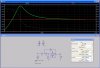
I designed my bass boost circuit long before this Australian guy published his circuit on the web but they are the same. Maybe he copied mine.
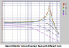
The circuit is an active second-order highpass filter with positive feedback higher than a flat Butterworth filter so it has a resonant peak.
That's mostly gobbledygook, which is pretty standard for you. It's a high-pass filter, so tell us, in words we can all understand that actually explain something, how it can have a resonant peak. What is a resonant peak, in your understanding, anyway?