Continue to Site

Welcome to our site!

Electro Tech is an online community (with over 170,000 members) who enjoy talking about and building electronic circuits, projects and gadgets. To participate you need to register. Registration is free. Click here to register now.

  • Welcome to our site! Electro Tech is an online community (with over 170,000 members) who enjoy talking about and building electronic circuits, projects and gadgets. To participate you need to register. Registration is free. Click here to register now.

Missing A2?

Status
Not open for further replies.

thePoopsmith

New Member
Hey All,

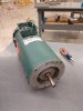
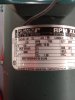
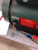
Looking for some help. Have a Reliance Electric brushed DC motor. FR# LG0056HC 1.25HP 120V 10A ID# 7343143-00 T3 -CK
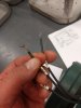
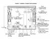
Have 5 wires coming out of it. A1, S1, S4, P1, P2. Resistance readings: A1 to S4 4.4 ohms. A1 to S1 4.2 ohms S1 to S4 2.2 ohms. P1 to P2 is closed, and I feel its the thermal overload. (different diameter wire) Im trying to hook it to a KBIC-125 motor controller with the extra heat sync. I expect the "A" wire(s?) to be the Armature, and "S" to be the field... but where is A2? I have the schematic for the controller, but cant seem to find any info on the motor. Can anyone offer any suggestions? Appreciate any help!
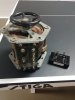
 

Attachments

  • IMG_20181203_112208450.jpg
    IMG_20181203_112208450.jpg
    937.7 KB · Views: 126
  • IMG_20181203_112155766.jpg
    IMG_20181203_112155766.jpg
    480.7 KB · Views: 130
  • IMG_20181203_112213695.jpg
    IMG_20181203_112213695.jpg
    804.5 KB · Views: 115
  • kbic-125.png
    kbic-125.png
    126.5 KB · Views: 120
I suggest doing some more resitance measurments to try to get a better picture of how it is wired internally. Remove both brushes and repeat the tests that you have allready done but also test beween each brush holder and each of the wires.

Les.
 
LB= Left Brush RB=Right Brush
with both brushes removed

LB - A1 = open
LB - S1 = 1.2 ohms
LB - S4 = 1.4 ohms

RB - A1 = continuity
RB - S1 = open
RB - S4 = open
 
When you make those resistance measurements.....

Connect your ohmmeter leads directly to each other. If the meter does not read zero, record (and post) the value you do get. Then make the measurements carefully. [An offset in the measurement can make it hard to determine the internal wiring.] Also, "Closed" and "continuity" are a bit too subjective - put a number on them.
 
I was expecting this to be a shunt wound motor but it seem to be series wound. A1 is connected to the right hand brush holder. (I assume by continuity you mean almost zero ohms.) As the the reading between S1 and the left brush holder and S4 and the left brush holder are 3 ohms less than between them ad A1 when the armature is fitted then it looks like the resistance between the brusholders with the armature fitted is 3 ohms. It looks like there are two field windings connected to the left hand brush holder. The thing that does not make sense for this picture is I would have expected the resistance between S1 and S4 to be 2.6 ohms. You got a reading of 2.2 ohms. I have not seen a series wound motor with two field coils connected to the same brush holder. Also series wound motors ar normally rated to run on both AC and DC. I dont think the speed contoller you have will work with this motor as they are normally used with shunt wound or permanent magnet motors. I will have to look on the internet to try to fined information on this type of motor or hope someone else replies that used this type of motor.

Les.
 
It says on the motor plate it is "Split series" wound.

That may mean it has a centre-tapped field with the tap connected to one brush.

It's a setup that allows direction control by using the brush/armature connection (A) and selecting one or the other field connection (the S wires) as the other power connection, without changing the supply polarity.
 
That sounds like a good possibility. The OP could test that theory using a 12 volt supply (Say a car battery.) connect one terminal of the battery to A1 and try connecting the other terminal to S1 then to S4 and see in then rotates in the opposite direction.

Les.
 
Sorry guys, got covered up. Yes the leads together on the meter at work were reading .5 ohms. I can do the tests that were suggested tomorrow. I'll take my fluke meter to work and get some more readings as well. Appreciate all the help and suggestions.
 
On the assumption that the readings you posted where the actual meter readings rather than the corrected values after subtracting the meter lead resistance. If we now make the correction then.
Test ------------- reading ------- corrected reading
LB to S1 -------- 1.2 ohms ------- 0.7 ohms
LB to S4 ------- 1.4 ohms ------- 0.9 ohms
S1 to S4 -------- 2.2 ohms ------- 1.7 ohms
NOTE I had to add the line of dashes to keep the table layout as the forum software removes multiple space characters.

This then explains why the with the original readings LB to S1 + LB to S4 (1.2 + 1.4 = 2.6 ) did not equal S1 to S4 (2.2)
With the corrected readings LB to S1 + LB to S4 (0.7 + 0.9 = 1.6 ) which is within the resolution of the readings very close to S1 to S4 (1.7)
Series motors have very poor speed regulation. To control the speed is more complex than shunt or PM motors as an external speed sensor is required to close the feedback loop. I suspect that the motor may not be suitable for your application. What do you plan to drive with it ?

Les.
 
Well Les, to be honest, the application is to be determined. :rolleyes::) I just love to tinker. The motor was a freebie. I purchased the controller used off of ebay for about $65. The motor was originally part of a training board setup used by a mining parts supplier. It has never had any load application. I was just curious if I could get it to work. The thoughts included possibly a DIY lathe, bandsaw for both wood and metal, large disk sander... etc. Some that dont necessarily require precision speed control or any control at all. I just thought that if I could control it, it would open up more applications. If the KBIC-125 wont work in this application, then its no biggie. Ill just hang on to it. If the motor is wired internally as you guys suspect, I also have a large Powerstat and a 100A full wave rectifier. I could switch it so that I could get forward and reverse.?? SPDT? (more applications :eek:) Pics attached. Ill head up to the shop where the motor is at shortly. Appreciate the comments!!!
 

Attachments

  • IMG_20181204_072724784_LL.jpg
    IMG_20181204_072724784_LL.jpg
    1.9 MB · Views: 122
  • IMG_20181204_072732170_LL.jpg
    IMG_20181204_072732170_LL.jpg
    922.9 KB · Views: 119
Interesting... here are some readings with my Fluke 12b meter.
Wires touching on meter 0- .1 ohms

Brushes In -
A1-----S1----2.7ohms
A1-----S4---2.6ohms
S1-----S4---1.5ohms

Brushes Out-
LB----A1---open
LB----S1---.3ohms
LB----S4--.4ohms

RB----A1---0 ohms
RB----S1---open
RB----S4--open

Took a jump start pack to the shop to test. Voltage read on pack was 12.3VDC

A1 to + terminal S1 to - terminal motor rotated counter clockwise
A1 to + terminal S4 to - terminal motor rotated counter clockwise at same apparent speed as A1,S1
A1 to + terminal S1, S4 together to - terminal motor rotated clockwise at same apparent speed as A1,S1 or A1,S4 but possible more perceived torque.??

Here is the interesting part...
A1 to - terminal S1 to + terminal motor rotated counter clockwise
A1 to - termainal S4 to + terminal motor rotated counter clockwise same speed as A1,S1
A1 to - terminal S1,S4 together to - terminal motor rotated counter clockwise.

Could NOT change direction of motor to clockwise with any wiring config.

Is the second field for maintaining torque at lower speeds???
Again, thanks for your inputs!
 

Attachments

  • IMG_20181204_083154336.jpg
    IMG_20181204_083154336.jpg
    837.8 KB · Views: 126
Last edited:
That seems to disprove rjenkinsgb theory which seemed to be the most reasonable explanation. as the two field windings have about the same resistance it is reasonable to assume they have about the same number of turn. (It would be interesting to know if both windings used the same gauge wire to see if that assumption is valid.) I don't think connecting the two field windings in parallel would make much difference as the current would be shared between them so the numbert of amper turns would be about the same. If you have a tachometer available it would be interesting to know if the motor rotated at the same speed for the S1 connection as the S4 connection and also with both connected.

Les.
 
Got a response back from a motor manufacturer...

Hi Brian,

A split series motor is a dual rotational motor, whereas a series motor is a single rotation motor. Split series has 3 leads, one is common (armature circuit), and the other two are field winding connections. Lets say armature is A, and fields are S1 and S2. If you connect the common (A) to line, and one of the field leads (S1) to line, and the S2 lead not connected to anything, it would run in one direction. If you want to run the opposite direction, interchange S1 and S2. Hope this helps.

Thanks,
Dan Barz
DC MTRS LLC

This supports rjenkinsgb's idea, so I asked Dan about the motor not changing rotation... His response -

Brian,

These motors are not polarity sensitive. If I were to guess at it without seeing it, I’d say you have a shorted field and that maybe the reason for no rotation change.

Dan

So Ill move forward with a little more testing and see how it goes.
Appreciate everyone's help so much!
 
I think that the ends of one of the field windings have been connected the wrong way round at manufacture. To correct this fault you will need to open up the motor and reverse the connections to one of the field windings (It does not matter which one.) I expect there to be two wires connected to what we have called the left brush holder. Disconnect one of them and identify the other end of that field winding using resistance tests. The other end of that winding (S1 or S4) will need to be connected to that brush holder and the wire you have unsoldered will have to be extended to the outside of the motor and will now be the correct S1 or S4. I agree with the comment that it is not polarity sensitive but I dont believe a short on the field winding would cauase it to behave the way it does. With this information I don't think you need to do the tests with the tachometer.

Les.
 
Status
Not open for further replies.

Latest threads

New Articles From Microcontroller Tips

Back
Top