Jon Wilder
Active Member
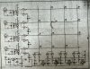
As I had questions about this myself I thought I'd post a helpful diagram for anyone who might happen to wonder how to properly hook up a 6N138 optoisolator as a MIDI Input. This diagram shows both the MIDI In and the MIDI Thru. A MIDI Out is identical to a MIDI Thru, however the input to the first Schmitt Trigger inverter is tied to the UART TX rather than the UART RX. This allows you to send the same OR different data from the UART TX to the MIDI Out rather than just mirroring the incoming data from the MIDI In like the MIDI Thru does.
The 1K resistor from pin 7 to ground is required for the quickest rise/fall time of the output transistor as you only have 32uS per byte. It can be 1K or higher. Some have used values as high as 22K here.
Hope this helps anyone who has this question -
**broken link removed**
The 1K resistor from pin 7 to ground is required for the quickest rise/fall time of the output transistor as you only have 32uS per byte. It can be 1K or higher. Some have used values as high as 22K here.
Hope this helps anyone who has this question -
**broken link removed**
")