Continue to Site

Welcome to our site!

Electro Tech is an online community (with over 170,000 members) who enjoy talking about and building electronic circuits, projects and gadgets. To participate you need to register. Registration is free. Click here to register now.

  • Welcome to our site! Electro Tech is an online community (with over 170,000 members) who enjoy talking about and building electronic circuits, projects and gadgets. To participate you need to register. Registration is free. Click here to register now.

Microwave frequencies emitter circuit

Status
Not open for further replies.

Nayldev

New Member
Hello,

For my project I need to build a variable frequency emitter, with a frequency between 100MHz and 3500Mhz.
I saw some simple RF circuits on the Internet but I don't think they can reach such high frequencies.

Here is a circuit I've found :
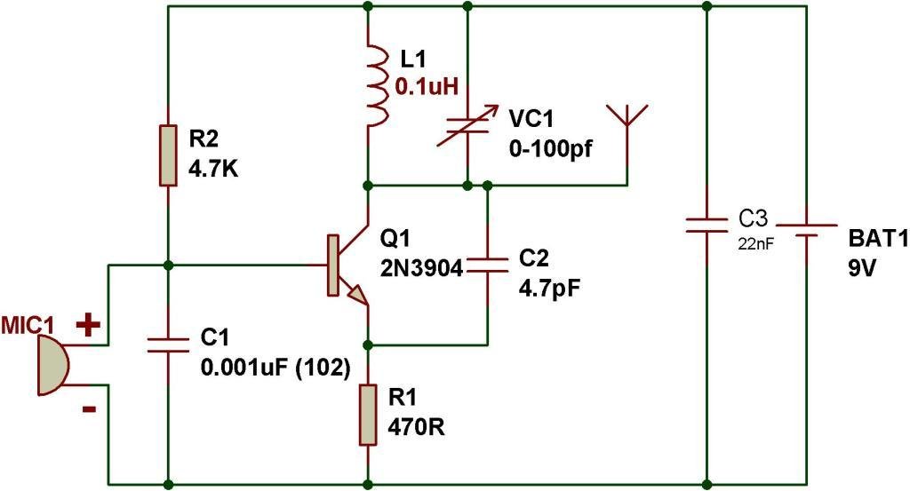
Fm-transmitter-Copy.jpg


I don't need to transfer any information, so I can get rid of the mic.

I guess that I have to change the inductance and/or the capacitance of the variable capacitor to reach higher frequencies.

But what about the other capacitors and the transistor? Do I have to change them?

And if I want to increase the emission power :
Does a simple increase of the input voltage increase the emission intensity? Or can it break some components?

Thanks in advance for your answers
 
That design is just a 'toy', it's the worst possible VHF transmitter you can find, highly unstable and drifts all over the place.

Even worse are microwave frequencies, VERY, VERY difficult to design and built, and it's more art and plumbing than electronics.

Your massive required range (0.1GHz to 3.5GHz), is also going to be pretty tricky as well.

You've also got the added problem, that even if you could built such a device, it's highly illegal.
 
When you say "with a frequency between 100MHz and 3500MHz" do you mean to say that it will operate on one frequency anywhere in that range, or do you mean that it must be adjustable to any frequency in that range? If the former, then use the example circuit as-is at 110 MHz. If the latter, then you are facing a considerably more difficult problem. It is very difficult to make a signal source that can be set anywhere in such a wide range, and I don't believe it can be done with a single oscillator circuit such as you show in your example. In the distant past, when faced with such a requirement, the most common approach was to have a number of tank circuits available that can be connected, one at a time, into the circuit using a switch. Such an approach becomes problematic above 500MHz or so because the parasitic reactance of switching circuits starts to dominate the oscillation frequency. Indeed, this assumes you can find a suitable transistor which is also non-trivial. You need a transistor that has sufficient gain at 3.5 GHz to allow oscillation, so something considerably more exotic than a 2N2222, for example. A transistor with good gain at 3.5 GHz may have too much gain below 1GHz making it difficult to maintain steady oscillation without spurious behavior and instability.

The most bullet-proof way to achieve this will require an architecture containing many more circuits than a single oscillator. For example, it might include a synthesizer controlling one or more microwave VCOs (switched one at a time) followed by sufficient translation, multiplication and division to move the VCO output into a band within your desired range. This is pretty advanced stuff.

If you are not experienced with RF and microwave design, you might be better off trying to get an oscillator that puts out the range between 100MHz and 200 MHz rather than 3500 MHz. Another alternative might be to try building individual oscillators for the following bands: 100 to 200MHz, 200 to 400MHz, 400 to 700 Mhz, 700 to 1200 MHz, 1200 to 2000 MHz, 2000 to 2600 MHz and 2600 to 3500 MHz and build each with its own separate output connector.

Another approach, if output level and fidelity are not very important, might be to build an oscillator that can be tuned from 100MHz to 200MHz and follow that with a frequency multiplier circuit to switch in various multipliers. It is practical to use a doubler to change the 100-200 MHz output into a 200-400MHz output. It is also practical to implement a tripler to take 100-200 and change it to 300-600MHz. This idea can be pushed as high as x5 with very astute choices of multiplier circuits, which ultimately will get you up to 1000MHz. Multipliers are, in theory, simple circuits. They usually consist of a non-linear device to generate harmonics, followed by a filter to select the harmonic of interest. The non-linear device could be a diode. The most common multiplier that I have seen is a transistor amplifier (common emitter) with a tuned output (using a tank circuit), that is biased to operate class B or C in order to operate non-linearly and with the collector tank tuned to the harmonic of interest. If you successfully built such a multiplier system, you would also have to figure out how to switch various multipliers in and out of circuit to give you the flexibility of tuning anywhere in your target range.
 
You've also got the added problem, that even if you could built such a device, it's highly illegal.
I agree with Nigel's comments except for the claim that such a device is highly illegal. This is an oversimplification. Illegality depends not on the existence of a hand-made device like this, but rather what you do with it. Illegality also depends on your location because what is or is not permitted by law is a function of what country you are in. In most developed countries building such a hand-made device is not illegal. In fact, many governments encourage experimentation. Selling such a device to other people without government approval is illegal. Connecting it to an antenna and transmitting its output over the air is almost certainly illegal without a license of some sort. Operating it without an antenna (such as if it were used in an enclosed application like RF heating for example) would require that you not allow it to radiate very much signal outside of the enclosure. Limits are defined for such unintentional radiation in each country's radio rules.

I encourage you to build such a device for fun and to improve your knowledge and skills, but do not put it on the air as a radio transmitter except briefly to try it out. It would probably interfere with somebody else if you use it for more than a brief time. There are exceptions in government rules that allow you to use it for a longer time, but these exceptions restrict you to specific frequency bands and to fairly low levels. The example circuit that you showed is designed to fit into one of those exceptions. You can learn more about the exceptions appicable to the USA by reading the FCC rules, part 15:

 
Thanks for your answers.
Actually I don't necessarily need such a wide frequency range, I can take only 2000MHz - 3000MHz for example
 
If you google "ADF4351 evaluation board" you will find numerous devices with will generate frequencies between 35MHz and 4300MHz.
The output power will only be 3 or 4mW, and the signal will be a square wave, ie it will have lots of 3rd, 5th, 7th, 9th etc harmonics, so if you wand a clean single frequency signal, you will need a low pass filter to cut the harmonics and generate a sine wave.

JimB
 
Thanks for the links!

I searched "ADF4351 evaluation board", and yes they say it generates frequency from 35MHz to 4300MHz, but I don't understand how to use it.
How to set the frequency and how do we use the output signal? Do I connect it directly to the antenna?
Do I need an Arduino? Or is there a simple way to use it?
 
How to set the frequency

For modules like this one, you need to use some kind of micro-controller to send data to the module,
1612213504719.png


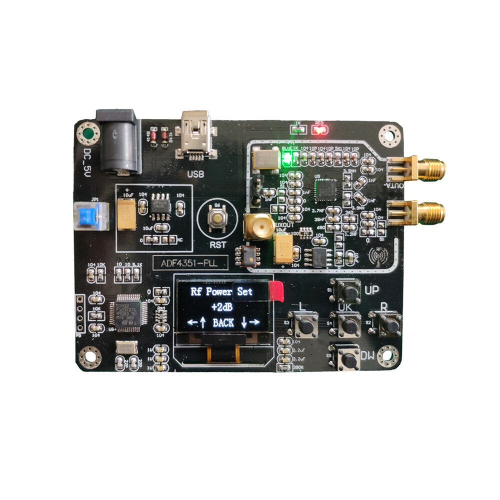
or, there are some modules like this one

1612213898879.png


which have a micro and user interface built in.


and how do we use the output signal? Do I connect it directly to the antenna?
I guess that all depends on what it is that you want to do with it.

What is your application for this signal?

JimB
 
This one looks good :

115c4c21-ea8d-42c3-a258-231ef029bd63.jpg

b8bf5deb-ee71-44fc-983e-047f767a96ad.jpg


Also, it allows to sweep through the frequency range, and that's mainly what I want to do.

I want to use the signal to emitt an electromagnetic wave.
So do I have to simply connect a wire or a piece of metal to one of the output plugs? (Out A+ and Out A-)
 
I want to use the signal to emitt an electromagnetic wave.
And that is where legality is involved. If the radiation causes interference with other users of the radio spectrum you could be in trouble.
How will you detect any emitted wave?
 
I can do everything in an enclosed box, with aluminum foil so no problem.

Then I also have a build a receiver, to have the intensity of the signal
 
I want to use the signal to emitt an electromagnetic wave.
Why?
What is it that you are trying to do?

I can do everything in an enclosed box, with aluminum foil so no problem.
Really?
You have a screened room?

Then I also have a build a receiver, to have the intensity of the signal
I would be interested to see the circuit of this receiver.


So do I have to simply connect a wire or a piece of metal to one of the output plugs? (Out A+ and Out A-)
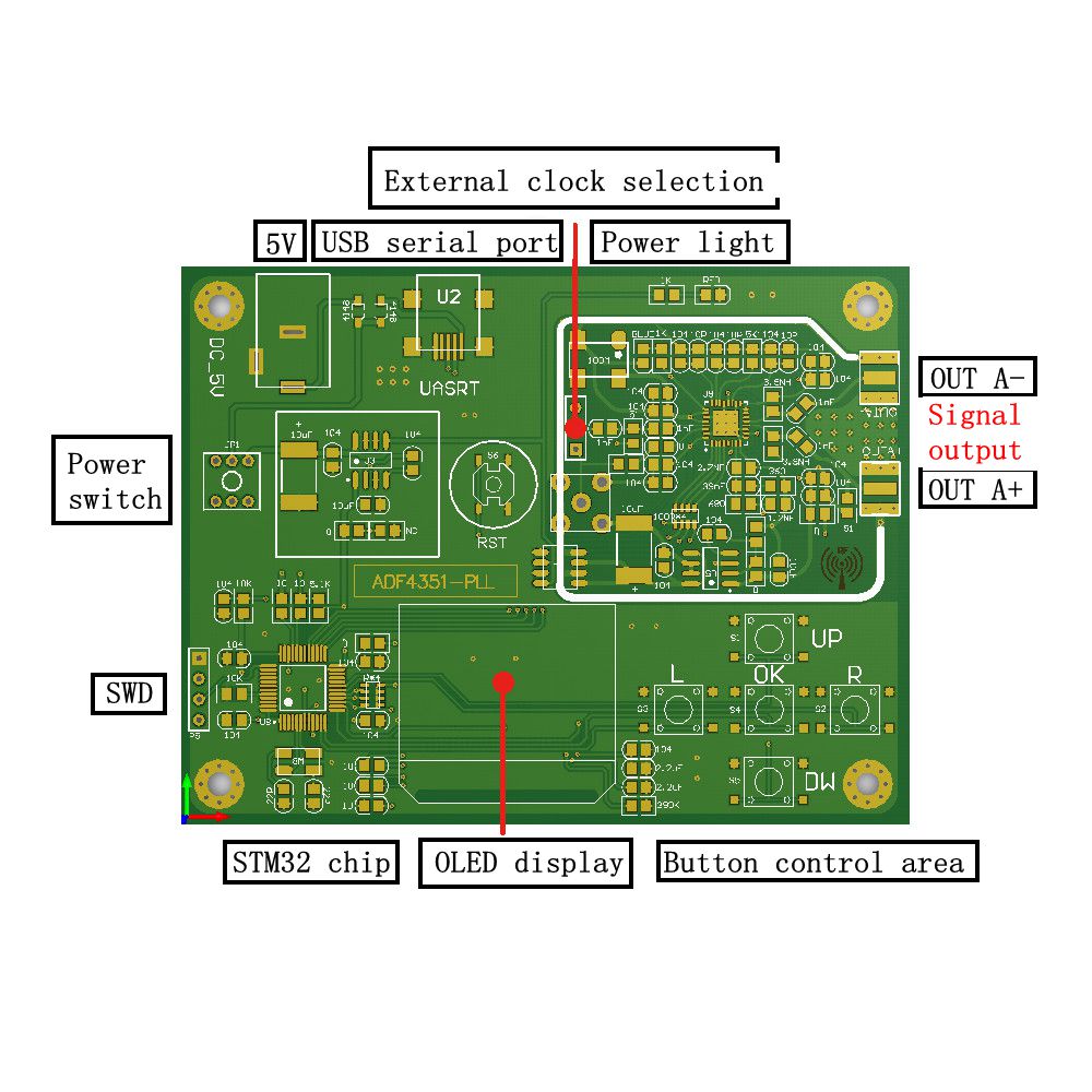
The ADF4351 has two outputs, A and B.
Each output has a + and a -.

Simple modules like those which I have shown, and the one which you have shown, only use the A+ and A- outputs.
The idea is that you can combine the + and - outputs using a suitable transformer or coupler.

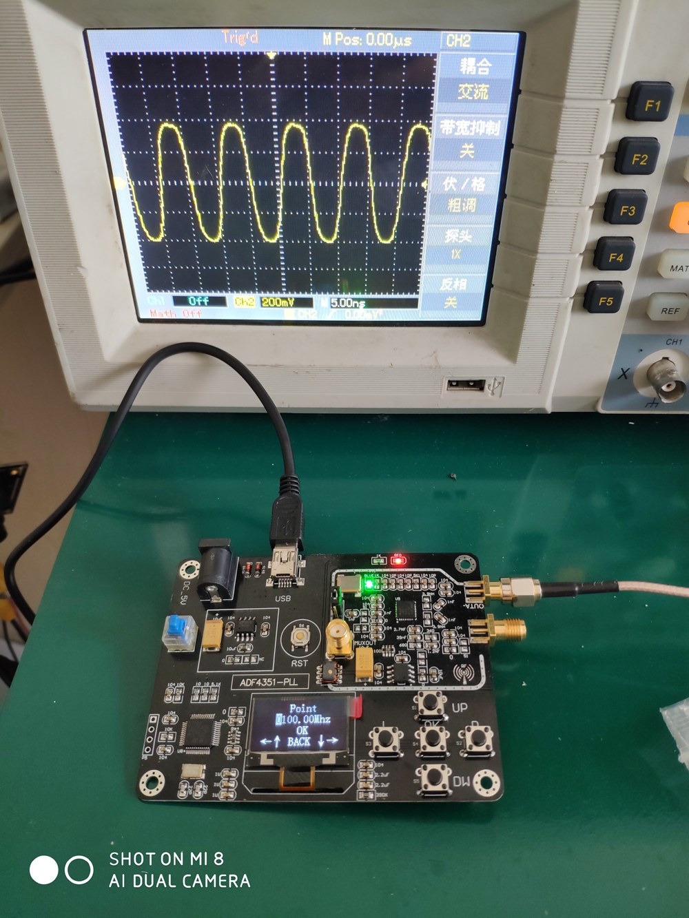
For simple applications, you can use either the A+ or the A- output on its own, like in this picture...
ADF2.jpg


Where the 100MHz output from the OUTA- connector is being displayed on the oscilloscope.

When I have been experimenting with these ADF4351 modules I have used one output to connect to my frequency counter and one output to connect to my spectrum analyser.

JimB
 
Thank you for your explanations.

I would like to get the absorption spectrum of chemical products, the idea would be to put, in a box covered with aluminum foil, the emitter on one side, the product in the middle and the receiver on the other side.

I still need to figure out have to make the receiver, but I think, and hope, that it will be quite easy, and any RF receiver could work.
 
This one looks good :
having over 40 years experience with looking at sine waves on oscilloscopes, i can tell you for sure that waveform has a lot of third, fifth, and 7th harmonic energy in it... it resembles the distorted sine wave you see from a vacuum tube amp as it's just going into clipping.... that waveform would need a bit of filtering out of harmonics before it would be usable as a radio signal.
 
i can tell you for sure that waveform has a lot of third, fifth, and 7th harmonic energy in it...

Earlier, JimB said:
the signal will be a square wave, ie it will have lots of 3rd, 5th, 7th, 9th etc harmonics, so if you wand a clean single frequency signal, you will need a low pass filter to cut the harmonics and generate a sine wave.

The output of the ADF4531 is basically a square wave.

JimB
 
I would like to get the absorption spectrum of chemical products, the idea would be to put, in a box covered with aluminum foil, the emitter on one side, the product in the middle and the receiver on the other side.
Interesting.

I still need to figure out have to make the receiver,
Try this:
**broken link removed**
A simple logarithmic signal level detector.

JimB
 
A simple logarithmic signal level detector.

Thank you for the reference!
So I guess I have to plug an antenna, and the voltage between the 2 pins of OUT is proportional to the signal strength, according to them...
But how to get the actual received power in Watts?
 
Status
Not open for further replies.

Latest threads

New Articles From Microcontroller Tips

Back
Top