Continue to Site

Welcome to our site!

Electro Tech is an online community (with over 170,000 members) who enjoy talking about and building electronic circuits, projects and gadgets. To participate you need to register. Registration is free. Click here to register now.

  • Welcome to our site! Electro Tech is an online community (with over 170,000 members) who enjoy talking about and building electronic circuits, projects and gadgets. To participate you need to register. Registration is free. Click here to register now.

Microcontroller reset

Status
Not open for further replies.

leonel

New Member
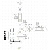
I'm using a PIC and the MCLR pin needs to be at +5V. I had this circuit (see figure) to in normal operation my microcontroller stays on, if i want to make a reset i push the switch, and goes to 0V. I want to know if this ciruit is right or maybe i will get any problem.
 

Attachments

  • push_down.jpg
    push_down.jpg
    25.2 KB · Views: 917
Yeah the diode isn't helping.
I thought the cap was supposed to go on the pin itself.

Really just a 10k pullup to 5v and a pushbutton to ground should do it. I know Microchip put out some docs for very complicated stuff but few if any really need such a thing. In fact most of the stuff can make things worse for the reset pin. So, just a resistor and pushbutton.
 
You don't need the diode and capacitor as others have written. However, MicroChip recommend a resistor between 50 and 100 Ohm where you have the 100 Ohm. I use 68 Ohm as it is near the centre of that range.

This is to prevent the possibility of lock up. So it is a worth while safe guard.

You can use the internal reset at power on. Enable the PWRTE bit.
 
Sorry, but my english it's not very good... What's the meaning of "lock up"?
I implemented my first circuit and sometimes, not always, when the load starts "running" my pic seems that does a reset.
You thing that might be a problem because of that circuit?
 
Someone else may be able to explain this better than I, but my understanding is that the PIC hardware goes into a state that it cannot escape from. So it does nothing while in that state. The only way it can escape from that state is when the power supply is removed.

I think that the problem you allude to is due to the Watch Dog Timer. The WDT causes a reset after about 18 ms (in the 16F84) so you need to turn it off. This is set in the configuration bits.

In the 16F84, you set bit 2 to 0 (see the data sheet section 6.0 Special Features of the CPU)
 
When I build processor circuits, I always use a similar configuration (minus the diode and the 100R resistor marked R8). However - in the schematic, the capacitor is reverse polarized. That is, if the program you used to draw the circuit uses "A" to represent anode and "K" to represent cathode (like on the diode).
JB
 
You're right... my schematic capacitor it's wrong, but in my board it's ok.
I don't think problem it's with Watch dog timer, because i already turned it off and my problem still happens!
I read datasheet and one reset may occur if brown out reset it's enable (pag. 94). If i put Brown Out detect OFF in MPLAB could solve my problem??? (i already didn´t test because i didn't have time...)
What dou you think?
 
leonel said:
You're right... my schematic capacitor it's wrong, but in my board it's ok.
I don't think problem it's with Watch dog timer, because i already turned it off and my problem still happens!
I read datasheet and one reset may occur if brown out reset it's enable (pag. 94). If i put Brown Out detect OFF in MPLAB could solve my problem??? (i already didn´t test because i didn't have time...)
What dou you think?

Hi Leonel,
You need to remove(short) the diode to reset the PIC from the pushbutton. With the diode inserted, the reset input on the PIC will be kept 'hanging' somewhere between 5V and 0v. If you then disable all the internal resets, the processor will not be reset properly.

The 'load' you write about that is causing the PIC to misbehave, what type of load is that? If you use some form of inductive load you need to take care of the induced spikes when you turn the load off, sometimes on also.

What type of power do you use to supply this system?

TOK ;)
 
Hi!
I already removed my diode and still happens!
I know that my problem might be with my load, but i already put a X2 47nF capacitor, but my problem still happens, specially with a hair drier as load. I don't know what to do more to solve my problem...
 
leonel said:
Hi!
I already removed my diode and still happens!
I know that my problem might be with my load, but i already put a X2 47nF capacitor, but my problem still happens, specially with a hair drier as load. I don't know what to do more to solve my problem...

Hi Leonel,
You don't say anything about how you connect your loads and what sort of power you use? If you are using relays you need to short the reverse spikes with a diode.

If you use long leads for power and signals the noise from a motor (hairdryer) is easily picked up in these. Your capacitor may also result in worse conditions if placed wrongly?

And last, when is your circuit resetting? At some specific point in the sequence, or it is random? What is running when it happens? Have you tried to simplify your program and make it completely bullitproof?

The quality of your information is the base for any valid answers!

TOK ;)
 
As previous posters have said without a schematic of the circuit we can only guess at answering your problem. This problem sounds like you don't have a de-coupling cap on the pic :?: but without any info we're only guessing so provide a whole schematic of the circuit and one of us can probably sort out the issue.

Cheers Bryan :D
 
leonel said:
I don't think problem it's with Watch dog timer, because i already turned it off and my problem still happens!
I programme my PICs with "icprog" and the watchdog timer can be set or cleared by ticking a box before programming. So it is easy to check if the WDT is on or off before programming.
 
Schematic

Sorry to be out of this thread so long...
Here is my schematic (attatched).
I already did a simple program and it has the same problems.
 

Attachments

  • 452promd1-1__schematic_design.pdf
    152 KB · Views: 169
In the begining of the thread i put a reset circuit... Some of you said that the diode was not helping, so i take off the diode, and this solve half of my problem, because now happens "sometimes", it's not always...
What more i can do?
 
This is what I say you try. Leave the diode so that it does during in-circuit programming the PIC is not affected.

Move the reset circuitry tafter the diode, and remove R8. R38 is a 100K pull down resistor that should not be there since the reset line is active low.

Make sure that the bypass capacitor C20 is really close to Pin 20 od the PIC. Physically, the line coming from +5V1 should hit the cap first and then the PIN 20. Just having pin 20 connected to +5V1 and then to the capacitor does not work efficiently.

You will need to add more filtering caps. In your power supply to try to elimite the noise created by the load. And you may want to use a optoisolator on the PIC outputs or at least some diodes.

Good luck,


P.S. To be able to see the schematic, you need to save the target in your
computer, then open it once it has "downloaded"
 
Status
Not open for further replies.

Latest threads

New Articles From Microcontroller Tips

Back
Top