Hi spec,
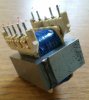
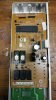
I don't think power rating will be any problem wth the transformer supplying the 3 volts. I think I would prefer using resistors to drop the voltage in this case as calculating the RMS voltage of the odd shapped waveform that would be produced using diode droppers would be difficult. (We need consider the RMS value as it is used to heat the filament.) The 35 volt winding will only be supplying about 25 mA. (The votage on the reservoir capacitor will be close to 50 volts on peaks and there ia 1K limiting the current to a 24 volt zener. I notice that this capacitor is only rated at 50 volts which puts things close to the limit. I think that the 13 volt winding will need to supply at least 500 mA as it drives a number of relays. I was thinking if we used a toroidal transformer for the 13 /12 volts then we could wind on an extra winding for the 3 volts. I would guess it would be about 6 turns per volt so we would only need about 18 turns. We would have to be sure the hole in the middle of the toroid was not filled with resin for mounting it.
Les.