Continue to Site

Welcome to our site!

Electro Tech is an online community (with over 170,000 members) who enjoy talking about and building electronic circuits, projects and gadgets. To participate you need to register. Registration is free. Click here to register now.

  • Welcome to our site! Electro Tech is an online community (with over 170,000 members) who enjoy talking about and building electronic circuits, projects and gadgets. To participate you need to register. Registration is free. Click here to register now.

Measuring

Status
Not open for further replies.

ScuzZ

Member
I have an output on a motherboard that illuminates a twisted wire LED(two pins).

Is there a way to measure the current(Amps) that this output is generating?
 
What does this wire do? If it's a signal wire, I don't think you could stick a small current sense resistor in series and measure the voltage drop across it to calculate the current...

Hall effect methods seem excessive just for this and I'm not sure if they work with such low currents.
 
I followed what I could find on google, but it's giving me inconsistant results.

It says make a break in the circuit, and hook the multimeter up. I'm assuming there should be about 10mA but my multimeter tells me there's 61mA. Im pretty sure that can't be right.
 
a Standard LED wouldn't last long at 61 mA's.
sure nothing else is connected to it?

Have you checked your meter at a known current?
eg. 5 Volts dc powersupply and connect a known resistor value across it and measure the current.
Allowe for a 5% error in the resistor.
 
There's nothing connected to it usually, on occassion the twisted wire LED for the front of the computer case.

I don't have anything to benchmark my results on. I've tried batteries but my multimeter says they're all Overload (Too high) and I don't have anything else to test it on.
 
I worked it out. I have an auto switching multimeter and I didn't even look at the range indicator.

It's actually 61 micro amperes. Which equates to 0.061 milli amperes.
 
That's what I thought. I'm not too sure that the auto ranging on this is right.

It reads 61 in the range of 100µA. So it could actually be 6.1mA.

I'm not completely sure how it reads the current.
 
You broke your meter by overloading it when you shorted batteries with it.
If it is set to measure DC current and is in series with the load, if the LED does not light then the meter's fuse is blown.

Why do you need to know the current of an LED? Maybe it is pulsing at a high frequency instead of DC.
If the LED is bright then its average current is about 25mA.
If the LED is dim then its average current is 2mA.
If the LED is extremely dim then its average current is next to nothing.
 
audioguru said:
You broke your meter by overloading it when you shorted batteries with it.
If it is set to measure DC current and is in series with the load, if the LED does not light then the meter's fuse is blown.
Exactly, I doubt it's broken, it probably just needs a new fuse.

I think the LED already has a current limiting resistor and you were just measuring the short circuit current.
 
What I done was take the LED wires off the motherboard and put the multimeter on the output(basic current measurement).

There's nothing wrong with the multimeter, it goes OL when its out of range(it auto selects up to a preset).

Im just having a problem with reading the range. I'm thinking if it's reading in the 100µA range, then the output could be in 100's. So it would have given me 6.1mA.
 
If a meter is in the 100uA range, then a reading of 61 is only 61uA which is nearly nothing.
My digital multimeters tell me if the reading is in uA, ma or A. Yours is so confusing that it should be replaced by one that was designed by a guy with some common sense.

You tried to measure the current with the LED shorted. The LED is not supposed to be shorted. A red LED is about 2V, a blue or white LED is about 3.5V. Their current would measure a lot higher if they had a resistor feeding the current and they are shorted with a current meter.
A current meter is supposed to be connected in series with the complete circuit.
 
I'm going on the information that was provided for me. Which is:

**broken link removed**

Where is states that the circuit must be BROKEN.

This is what I done.
 

Attachments

  • Diagram.JPG
    Diagram.JPG
    21.4 KB · Views: 158
Last edited:
You said that you took the LED wires off the motherboard then placed the meter's probes on the output.

But to measure current you are supposed to connect the meter in series between the current source and the load which is the LED. Then the meter is just a piece of wire and the LED lights with almost its normal amount of current.
 
Most DMM have two fuses, to protect two or sometimes three Amp ranges.
One 300 mA fuse for low mA an uA ranges, and another 10 Amp fuse for the readings up to 10 amps.

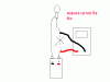
As i said in a previous post, test your meter on a dc powersupply connect a known value resistor to have a current flowing of 10 mA's or 100uA's to check your meters ranges.

to get 100 uA at 10 Volts you need to connect a 100 kOhm resistor in series with your meter across the 10 V dc from your powersupply.
for 10 mA at 10 V use a 1 kOhm resistor.

Then see what scale the meter shows, uA, mA, or .00 mA.

Most LED's will give a visual indication above 1 mA ( high eff LED's).
The older type LED's need at least 10 mA to show any sign of life.
 
ScuzZ said:
I'm going on the information that was provided for me. Which is:

**broken link removed**

Where is states that the circuit must be BROKEN.

This is what I done.

If I read this right, it sounds like you shorted the output with your meter. In current mode, a meter has very very low resistance (like in the milli ohms). You are supposed to break the circuit and insert the meter, but while the load is still attached...
 
lol He removed the led all together. You are supposed to break one side of the circuit, then put the meter in series with it, not break both sides of the circuit and put the meter in parallel. You must measure current in series with a load.
 

Attachments

  • current.GIF
    current.GIF
    4.3 KB · Views: 137
Thanks for all the great info.

So I'll take off the LED and put a known resister in it's place.

What formula do I use to work out what the amperage is?
 
Status
Not open for further replies.

Latest threads

New Articles From Microcontroller Tips

Back
Top