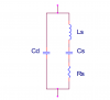
Another question which arises is. Why does an ultrasonic piezo sensor says to be an capaciotor or behaves as a capaciotor? The model shows that It is not just a capacitor, unless we say that in resonance frequency the Ls and Cs cancel each others and then we just have Cd and Rs, right?
A piezo sensor behaves as a fairly large capacitor with several resonant circuits more or less well coupled to the terminals.
Look at the circuit you attached to post #8; the equivalent value of Cd is large enough that its impedance is the dominant characteristic at all frequencies. This is because of the way the sensor is constructed. It is probably a disc (or some similar geometric shape) of piezoelectric ceramic material with conductive electrodes deposited on each side. That's exactly how ceramic disc capacitors are constructed. The difference is that the material in the piezo sensor is permanently polarized (see:
https://en.wikipedia.org/wiki/Electret), whereas the material in a ceramic disc capacitor is not permanently polarized. The piezo sensor is built just like a capacitor, so we shouldn't be surprised if its impedance looks mainly capacitive.
Now, the piezo sensor can vibrate mechanically and those vibrations can cause (or result from) a voltage at the terminals. But, since a disc (or other shape) can vibrate in many different ways (see:
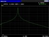
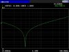
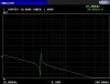
https://en.wikipedia.org/wiki/Normal_mode), we would expect to see many resonances in the impedance curve of the piezo transducer. The overall impedance of the piezo sensor trends downward as the frequency increases, which is characteristic of a capacitor.
The attached image shows the impedance vs. frequency of a Matsushita 40 kHz piezo sensor.
Typically, one series resonance/parallel resonance pair is dominant, and is the one we want to use. The other resonances are called "spurious" resonances.
When you ask about the "net" resonance, perhaps you are referring to the lowest frequency normal mode, the dominant resonance in a disc.
If the sensor (resonator) is a high Q device, the series and parallel resonances will be very close together, and detecting them separately will require the use of a signal generator that can be set to a particular frequency with a resolution of a few Hz, and doesn't drift when you take your hand off the tuning knob.