Continue to Site

Welcome to our site!

Electro Tech is an online community (with over 170,000 members) who enjoy talking about and building electronic circuits, projects and gadgets. To participate you need to register. Registration is free. Click here to register now.

  • Welcome to our site! Electro Tech is an online community (with over 170,000 members) who enjoy talking about and building electronic circuits, projects and gadgets. To participate you need to register. Registration is free. Click here to register now.

Measuring ~120 VDC on an Oscilloscope

Status
Not open for further replies.

ARE_ES

New Member
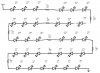
I have a set of LED christmas lights that I am trying to start a project with. The LED string comes with a power cord which is an A to D rectifier according to the manual that comes with the lights. A schematic of how the lights are hooked up is attached. I would like to hook up the supply to an oscilloscope to see what the waveform is like (I'm assuming there is some sort of PWM going on). I tried before, and began by trying to hook the ground alligator clip of the probe to the negative terminal of the output. There was a massive bang and flash of light, the fuse inside the lights power cord had tripped as well as seemingly fried whatever was inside because every time I plug it in after that the fuse trips. Luckily it seems the oscilloscope still works. What did I do wrong? How can I hook up the rectifier to an oscilloscope correctly?
 

Attachments

  • LED Christmas Lights Schematic.jpg
    LED Christmas Lights Schematic.jpg
    92.1 KB · Views: 1,007
The LED string comes with a power cord which is an A to D rectifier according to the manual that comes with the lights.
If the only components in the cord are a rectifier and a fuse then the LED circuit is not mains isolated and is dangerous. Your scope ground clip would, therefore, have shorted one mains terminal to ground. Considerable current can flow between mains neutral and ground (as well as between the live terminal and ground) and probably was the cause of the flash and bang. Always use an isolation transformer between the scope and any circuit under test which may be at mains voltgae, observing all the usual safety precautions regarding high voltages.
 
The usual way to do it is to put the scope in differential mode, DON'T connect the ground clips at all, use the inverting input probe as gound, and the non-inverting input to test.
 
Last edited:
Status
Not open for further replies.

Latest threads

Back
Top