Electro Tech is an online community (with over 170,000 members) who enjoy talking about and building electronic circuits, projects and gadgets. To participate you need to register. Registration is free. Click here to register now.
Welcome to our site! Electro Tech is an online community (with over 170,000 members) who enjoy talking about and building electronic circuits, projects and gadgets. To participate you need to register. Registration is free. Click here to register now.
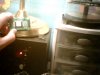
I just desoldered an MDK52V-O LCD Dipsplay from an IBM Memory Station. I would like to know the pinouts, and how to operate the thing. It does have a built on driver, and backlight. I have attached some pictures.
Its got the pinout, and looks to me to be a typical HD44780-type interface.
The website seems to use a USB interface, but of course a microcontroller would do just fine.
If its got 16-pins, then 15 and 16 will be the power for the backlight. If you don't know how to control it, there is a wealth of info about these types of LCDs (HD44780 equivilents).
I did google it, and i came up with nothing. Thanks, but i can't read japanese. Yes, it is 16 pins. 14 for the LCD, and 2 for the back light.
The controller is in fact an HD44780. So, will all of the pinouts be the same for all LCD's with the HD44780? I really want to start using this thing. it looks cool!
heh, turns out that is the standard pinout its just I've seen some HD44780 modules with different pins. If you haven't used this type of LCD before, its pretty easy, and as I said loads of info on google, whether you want to use it with a micro, or link it up to your PC with something like 'LCDsmartie'.
Well, judgiung by the few character LCD's I've got here (the ones with the double row connector on the left) pin1 appears to be bottom right. With pin 2 on the bottom left. This is looking directly at the dispaly, not the backside!
So, as you lok at the back of it, with the connector on your left, pin one is top right, pin 2 top left etc.. I believe this is the standard pin configuration.
This site uses cookies to help personalise content, tailor your experience and to keep you logged in if you register.
By continuing to use this site, you are consenting to our use of cookies.


 Yes, it is 16 pins. 14 for the LCD, and 2 for the back light.
  its just I've seen some HD44780 modules with different pins. If you haven't used this type of LCD before, its pretty easy, and as I said loads of info on google, whether you want to use it with a micro, or link it up to your PC with something like 'LCDsmartie'.
")