Continue to Site

Welcome to our site!

Electro Tech is an online community (with over 170,000 members) who enjoy talking about and building electronic circuits, projects and gadgets. To participate you need to register. Registration is free. Click here to register now.

  • Welcome to our site! Electro Tech is an online community (with over 170,000 members) who enjoy talking about and building electronic circuits, projects and gadgets. To participate you need to register. Registration is free. Click here to register now.

MAX7219 current draw?

Status
Not open for further replies.

Pommie

Well-Known Member
Most Helpful Member
I have a few 32x8 LED displays that consist of four MAX7219 chips coupled with four 8x8 LED displays (cheap ebay version). The current setting resistor (Rset) is 10K which equates to an LED current of ~40mA. I initially thought that a single display (8x8) would take 64*40mA which is 2.56A. The datasheet states ~330mA with all LEDs lit, I then realised that they're multiplexed and only one row/column is on at any time, hence 8*40mA = 320mA = close enough. However, four display (32x8) will take ~1.44A.

I have an Internet enabled clock that uses one (32x8 = four displays) display but now I want to build a new one with four (32x8) displays arranged as 64x16 LEDs. Assuming half the LEDs are lit (on average) then the current draw should be ~2.88A. My old clock is powered by a USB charger via a USB cable. This new clock will take too much power for a normal USB charger.

I'm thinking I'll need a separate power supply, probably 5V at >3A. I actually find the displays extremely bright so might limit the brightness to 50% which will reduce the current requirement to an average of 1.44A and an absolute maximum of 2.88A.

Having written the above I think I've answered most of the questions I had.

Any comments or corrections of the above very welcome.

Mike.
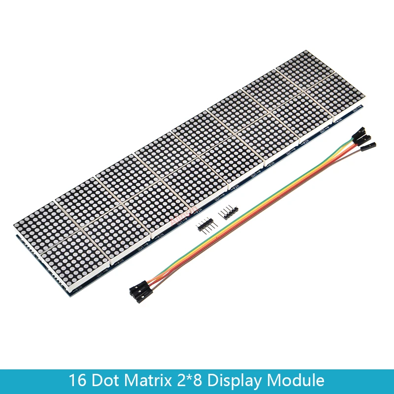
A link to a 64x16 display.
 
Sounds like you've got it. I love the MAX7319 drivers. They remove all the "busy work" from the micro.

BTW – a MAX7319 can share clock and data pins with I2C devices. The MAX7319 ignores date when /CS isn't asserted, and I2C devices ignore messages not properly addressed to the device.
 
I'm guessing your 7319 (I²C expander) is a typo. I know an I²C version of the 7219 exist but I've never used (or seen) it. The nice thing about the SPI version is you can daisychain as many as you need. The 64x16 displays have two strips of 8x8 displays but the DO (data out) from the top row has to be connected to the other end of the second row. Using I²C (I guess) would run out of addresses.

Going to try and use an ESP32 as I've found the ESP8266 a bit flaky. I want to get it communicating with a website that can also communicate with an App.

It'll be a fun project.

Mike.
 
I'm guessing your 7319 (I²C expander) is a typo.

I'm old and and it was the middle of the night Yes, that was a typo.
 
Post pic of finished product. Would love to see it!
This is my current clock with one 32x8 display.
clock.jpg


The 3 dots on the bottom line are the seconds indicator. As the display is 32 pixels wide, it starts at the left as 2 pixels, changes to 3 and then extinguishes the first pixel so it takes 60 seconds to complete the 32 pixel movement.

Mike.
 
Nice work.
 
This is my current clock with one 32x8 display.
View attachment 138355

The 3 dots on the bottom line are the seconds indicator. As the display is 32 pixels wide, it starts at the left as 2 pixels, changes to 3 and then extinguishes the first pixel so it takes 60 seconds to complete the 32 pixel movement.

Mike.
What about a flashing colon in the middle for seconds? :D

I've been doing a lot of work on the MAX7219 recently, and one experiment was (of course) a clock display.

While there's no space for a colon, it's easy to make space - simply move the first two digits left one column, and the right two digits right by one column - this leaves a perfect gap for a flashing colon. The numeric font is only six pixels wide, so allows space to do this.

You can do the exact same to add a decimal point as well, but in that case you need to make the positions of the digits leave the gap in the correct place.

Here are my experimental boards, as can be seen they have space for two 4x8 displays side by side - so far I've got a rather nice 'gym timer' project running on one. The mysterious hole in the middle, is for a piezo sounder, which is hot melt glued to the board.

IMG_0736.JPG
 
What about a flashing colon in the middle for seconds? :D
If you look the digits are 5 pixels wide so leaving 3 pixels between digits where the colon happily sits, just happened to be off when the picture was taken.

However, I really like your double pixel font, does give it a very chunky feel.

One problem with the 64x16 displays is the end of the top row (Dout) need to connect to the start of the second row (Din) and that's just messy. I'm thinking of making a board that will treat each row as a separate display with it's own unique CS so only one end of the display need a connection.

Another problem is that I can only find the large displays on Aliexpress (or Alibaba) with a minimum order quantity of 25 which makes prototyping a little expensive (and potentially wasteful).

Think I'll have to prototype one using 32x8 displays that I already have.

Mike.
 
If you look the digits are 5 pixels wide so leaving 3 pixels between digits where the colon happily sits, just happened to be off when the picture was taken.

Right, so you've space for a colon - mine wasn't a 'real' clock, I just threw a bit of code together to demonstrate the character spacing. However, I have had a clock running, with the colon flashing - using a half second interrupt flag to flash the colon, and a one second interrupt flag to update the clock display.

One problem with the 64x16 displays is the end of the top row (Dout) need to connect to the start of the second row (Din) and that's just messy. I'm thinking of making a board that will treat each row as a separate display with it's own unique CS so only one end of the display need a connection.

Aren't they already joined on the board?, the 32x16 ones are.

Another problem is that I can only find the large displays on Aliexpress (or Alibaba) with a minimum order quantity of 25 which makes prototyping a little expensive (and potentially wasteful).
Can't say I've seen any with minimum order quantities?, how about this one:

 
Looks awesome!!! Might have to try my own led matrix project. How are you driving it? Arduino, raspberry pi, or other?
Don't know about Pommie?, but I'm using a PIC 18F27K42 - for anyone interested, the power supply options on the board are a 7805 (for inputs over 5V?), or a Chinese 5V (USB) up-converter module for powering it from 18650's.
 
Aren't they already joined on the board?, the 32x16 ones are.
Did you mean 64x8? I.E. 8 boards linked as one row.
They are linked length wise but the end of the top row isn't connected to the start of the second row.
This is a picture of the back of a 64x16 display,
64x16.jpg

It's not clear from the image but they are all individual 8x8 displays before cutting up so the top line has Dout on the right which needs connecting to Din of the second line on the left.

The aliexpress display you linked is probably what I'll aim for.

Mike.
 
Did you mean 64x8? I.E. 8 boards linked as one row.
They are linked length wise but the end of the top row isn't connected to the start of the second row.
This is a picture of the back of a 64x16 display,
View attachment 138359
It's not clear from the image but they are all individual 8x8 displays before cutting up so the top line has Dout on the right which needs connecting to Din of the second line on the left.

The aliexpress display you linked is probably what I'll aim for.

Mike.
No, I meant the 32x16 ones (two rows of four modules) - I have a couple of those and the output of the first row links back to the input of the second. They don't tell you which two link together though, but it's trivial to find with a multimeter on low ohms.

On my 32x16 ones the input (as you look from the back) is the top right, and the top left connects down to the bottom right, with the pass through at the bottom left.

Get your meter out and check from Dout to Din on the outside connectors - it'd be strange if they weren't connected?.
 
Status
Not open for further replies.

Latest threads

New Articles From Microcontroller Tips

Back
Top