Continue to Site

Welcome to our site!

Electro Tech is an online community (with over 170,000 members) who enjoy talking about and building electronic circuits, projects and gadgets. To participate you need to register. Registration is free. Click here to register now.

  • Welcome to our site! Electro Tech is an online community (with over 170,000 members) who enjoy talking about and building electronic circuits, projects and gadgets. To participate you need to register. Registration is free. Click here to register now.

MAX712 NiMh battery charger problem

Status
Not open for further replies.
Is your V+ high enough?
From the datasheet :-
"Choose an external DC power source (e.g., wall cube). Its minimum output voltage (including ripple) must be greater than 6V and at least 1.5V higher than the maximum battery voltage while charging.
This specification is critical because normal fast-charge termination is ensured only if this requirement is maintained ".

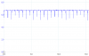
I'll give it another try in this afternoon but do you think that when current is flowing to the battery, voltage is dropping and causing the max to reset ?
 
Possibly. Or maybe the IC was damaged by the wrong connection.
 
Hello, I've got news ! thank you for your replies.

Well, I feel that I'm really close.

I took a new PCB, soldered new components and took a MAX713 chip from Mouser (last one, untouched till now).

I wired everything, from 6V to 8V (R1 changed to 150 Ohm), and I still have those "switching" pulses by measuring the shunt voltage.

I've also measured DRV pin, and it confirms the switching behavior.

Please find attached the schematics in better color, also the oscilloscope readings.

Can it be related to the PNP ? even if I don't think so...

I've checked voltages:
V+: from 4.5V to 5V when I raise input voltage
Vref and Vlimit : 2V
BAT+ = 2.8V on fastcharge
Temp voltages 100% corresponding to calculations done.

Any ideas ?

I really hope some of you will continue helping...thank you very much
 

Attachments

  • DRV_PIN_max713.png
    DRV_PIN_max713.png
    14.4 KB · Views: 195
  • fastcharge_max713.png
    fastcharge_max713.png
    20.6 KB · Views: 201
  • sheet.png
    sheet.png
    39.8 KB · Views: 195
I've did some calculations, and still don't understand as from the datasheet, to calculate C2 (current regulation loop capacitor) here are the equations:

BWCRLin Hz = gm/C2, C2 in farads,gm = 0.0018 Siemens
fBin Hz = fT/Bo, fTin Hz, Bo= DC current gain

BWCRL< fB

From MJD200 datasheet, picture attached.

And finally you'll find my calculations and results attached as well, on CC regulation table (picture attached & Excel).

I mean, I'm not just going there with random components and relying on your efforts to get things to work, I'm actively trying to understand why it doesn't work, and I'm trying to get your help in this scope.

Thank you.
 

Attachments

  • mjd210.png
    mjd210.png
    18.9 KB · Views: 192
  • cc regulation calculus.png
    cc regulation calculus.png
    7.1 KB · Views: 193
  • calc excel.zip
    102.7 KB · Views: 180
According to Wikipedia, "Under a light load (0.5 ampere), the starting voltage of a freshly charged AA NiMH cell in good condition is about 1.4 volts." So your BAT+ voltage seems reasonable.
 
I'm still not able to make understand where the switching is coming from, I'm upping this topic hoping that someone will read and give some advice.

Thank you very much.
 
I'm still not able to make understand where the switching is coming from
My guess is that there is something causing the input V+ to drop. As per p10 of the datasheet,
"When the input voltage at DC IN drops below the 1.5V + (1.9V x number of cells), the part oscillates between fast charge and trickle charge".
 
Dear alec,

Thank you for your advice, but I already investigated that, here is the result below.

I'm investigating VDRV voltage while changing VCC value to below limit value and then above it, as you can see, the behavior is different.

You'll see some kind of square wave when VCC is below 1.5V + (1.9V x number of cells).

When I raise VCC to the required value, instead of having VDRV going down, it switches between "low" and high value
 

Attachments

  • VCC_too_low.png
    VCC_too_low.png
    5.1 KB · Views: 196
  • VCC_correct.png
    VCC_correct.png
    6.2 KB · Views: 190
Have you 'scoped V+ to see if there are any transients there?
 
Hello,

Yep I've did it, first, monitored VCC and it was oscillating between 4.5V and 6.2V, then I added a big capacitor and it stayed very..very stable at 6.2V, but the DRV pin behavior persisted.
 
Dear everyone,

I've checked V+ voltage, and it's 4.8V, however from time to time I get some spikes up to 5.2V.

But anyway, V+ voltage it in the "normal" voltage....
 

Attachments

  • V+.png
    V+.png
    10.2 KB · Views: 194
I have a question that sounds maybe stupid, but in PNP transistor, do we agree that the collector goes to the diode and battery, and the Emitter is connected to VCC.

Because, I've reverted the transistor (emitter-collector) and wired it as a NPN one, and even if the switching behavior is still here, it somehow changed.

Current flowing to the transistor is higher and the ON pulses are longer, also, V+ voltage is stable.

I'm really tearing off my hair to know why is this happening and what's the rootcause of those switching pulses....

Picture of RSHUNT voltage (0.59Ohm) attached.
 

Attachments

  • reverse PNP_Rshunt_voltage.png
    reverse PNP_Rshunt_voltage.png
    7.9 KB · Views: 191
LOL Alec

You're "solid as a rock" when it comes to Technical advise. You know your stuff plus you have a sense of humor
Well,

I also sent a "good" version of the sheet in the discussion ! I'll attach it again here ;)
 

Attachments

  • sheet.png
    sheet.png
    39.8 KB · Views: 187
do we agree that the collector goes to the diode and battery, and the Emitter is connected to VCC.
Yes.
What load current are you drawing during the charge process? Is it an intermittent or continuous load?
What is the current rating of your wall-wart output?
 
Hello Alec,

The load is a 400mA DC motor, however, it's not connected yet to the circuit.

Current rating of Power supply, I have two of them:
-A wall cube adapter 6V 600mA
-A voltage variable power supply 20V max I guess for 30A, this power supply is used for all my projects.
 
very stable at 6.2V
I've checked V+ voltage, and it's 4.8V, however from time to time I get some spikes up to 5.2V.
Those statements are inconsistent :confused:.
Getting desperate here, but have you tried alternative batteries to see if the switching glitches occur with all of them?
Is a current limit set on whichever supply you are using?
 
Dear everyone hello !

I've news !

Sorry for not showing up for a long time, I had some real life opportunities to take!

Well, what I did now is to put everything on a proofboard, and the good think is that the issue is still here, which means it's repeatable and not related no layout/soldering.

BUT, I've tried to remove that MDJ200 PNP and replace it with small S9012 and the behavior changed completely.

Now the linear regulation is happening and I even tried with 2N3906 and I have the same result.

However I have two questions if you mind:

- Why the first transistor behaved the way it did ? (kind of pwm like the max was resetting)
- Why the Max is regulating the voltage to ~130mV instead of 250mV on the shunt ? (image related)
 

Attachments

  • Screenshot_7.png
    Screenshot_7.png
    24.4 KB · Views: 179
EDIT: Sorry for double message, it's an error.

Well, my bad as I rewired everything I switched between transistor collector and base which explains the behavior.

After correcting that, the switching behavior is still here.

As I'm on a proof board I can change pretty much everything, so I tried to raise (and reduce) current control capacitor, which lead to same result, except the time between two pulses that was shorter or longer.
 
Last edited:
Status
Not open for further replies.

Latest threads

New Articles From Microcontroller Tips

Back
Top