Electro Tech is an online community (with over 170,000 members) who enjoy talking about and building electronic circuits, projects and gadgets. To participate you need to register. Registration is free. Click here to register now.
Welcome to our site! Electro Tech is an online community (with over 170,000 members) who enjoy talking about and building electronic circuits, projects and gadgets. To participate you need to register. Registration is free. Click here to register now.
I have a square wave signal (50% duty cycle) with variable frequency and I want to control this signal to become square wave with 33% duty cycle in any frequency.
Does anybody can help what kind of circuit I can use?
You can generate an variable duty-cycle signal directly with a timer chip, or you can convert your square wave into a linear ramp, then feed it into the + input of a comparator with the - input being fed by a variable resistor connected between the rails. Use the variable resistor to vary the duty cycle.
If you want to do this automatically as the freq of the the square wave is varied, then use a phase-locked-loop with a divide by 3 counter between the VCO and one input of an edge-sensitive phase comparator. The other input of the phase comparator gets the original square wave. The output of the divide by three counter (phase comparator input) will have a 1/3 duty cycle.
The VCO will be operating at three times the frequency of the square wave.
You can generate an variable duty-cycle signal directly with a timer chip, or you can convert your square wave into a linear ramp, then feed it into the + input of a comparator with the - input being fed by a variable resistor connected between the rails. Use the variable resistor to vary the duty cycle.
If the frequency is very often to change, which one of the both solution is more accurate and have good stability ?
Because I must design in very small space ( 20 mm x 30 mm), do you know which IC is suitabel to do the circuit ?
If you want to do this automatically as the freq of the the square wave is varied, then use a phase-locked-loop with a divide by 3 counter between the VCO and one input of an edge-sensitive phase comparator. The other input of the phase comparator gets the original square wave. The output of the divide by three counter (phase comparator input) will have a 1/3 duty cycle.
The VCO will be operating at three times the frequency of the square wave.
Thanks for the idea using PLL, but if the frequency become more higher, is there no phase shifting comparing with in the low frequency ?
Which PLL IC is suitable for small space (20mm by 30 mm) ?
The frequency range from 0 Hz up to 2000 Hz and the frequency operation of the device is always changing all the time because it is to drive dc motor and it is not working at constant speed.
And the changes are nearly smoothly.
The frequency range from 0 Hz up to 2000 Hz and the frequency operation of the device is always changing all the time because it is to drive dc motor and it is not working at constant speed.
And the changes are nearly smoothly.
Can you modify the motor to output three pulses per shaft revolution? You could attach a disk with three (or multiple of three) holes, or three hall-effect sensors. That would eliminate the PLL. The divide by three counter would then have a 33% duty cycle with one cycle per revolution.
If the frequency is very often to change, which one of the both solution is more accurate and have good stability ?
Because I must design in very small space ( 20 mm x 30 mm), do you know which IC is suitabel to do the circuit ?
Can you modify the motor to output three pulses per shaft revolution? You could attach a disk with three (or multiple of three) holes, or three hall-effect sensors. That would eliminate the PLL. The divide by three counter would then have a 33% duty cycle with one cycle per revolution.
Dear Mike,
I can not modify the motor because it already have a driver system built in there. The circuit I want to design is just to give signal to the driver system with the specification of 33% duty cycle.
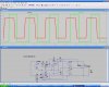
It seems easy, but it's not. Here is my effort. Essentially, U1 takes twice as long to ramp up as U3. Add the signals together, and you get a 1/3 - 2/3 duty cycle. U2 cleans up the edges.
I doesn't seem to simulate quite right. I think this would have to be built to tune up properly. It needs some more refinement. This is just an idea.
That is the real problem, the first time I see is look easy, but after I am trying to get the real solution I found not to easy to do that.
But thank's for your idea, I will learn it to try also for the solution.
Maferic, after sleeping on it, I realize my circuit won't give satisfactory performance over your frequency range. Also, it will exhibit a little lag when changing frequencies, which may or may not be a problem. I think it can be fixed, but fixing it would at least double the number of components and quadruple the design effort. In the end, it probably won't perfrom any better than the PLL idea. Unless you just don't want to use a PLL, that's probably your best bet.
The simplest, most reliable solution is to get the motor to put out three pulses per revolution...
Any PLL solution always will have a lag as the frequency changes.
You could use the Capture/Compare Timer in a PIC to implement the equivalent of the PLL logic in software/hardware. Use a Timer in the PIC to measure the time between successive rising edges of the squre-wave, divide the count by three, load the Compare register with the quotient, and then output a 1 on port pin while the timer is less than 1/3 of the previous period...
If comparing between PLL and PIC microcontroller, which one is more stable and reliable because the circuit are operating very close to the dc motor system that maybe causing spike signal. I worried using microcontroller have possibility hang up when getting spike. Pls give suggestion.
Suppress the spikes. Either method could be upset. The PLL is more likely to relock without a watchdog. Is the 33% duty cycle signal inside the control loop for the motor? If so, what happens if the PLL or PIC temporarily gets out of sync?
Suppress the spikes. Either method could be upset. The PLL is more likely to relock without a watchdog. Is the 33% duty cycle signal inside the control loop for the motor? If so, what happens if the PLL or PIC temporarily gets out of sync?
The signal are requiring for controlling the speed to drive motor rotating more higher speed / slower speed up to stop.
When out of sync I do not know exactly what will happen because the documentation of the motor control are not complete, but my opinion maybe it will lag (late response to drive the motor) and sometimes maybe really no response to drive.
This site uses cookies to help personalise content, tailor your experience and to keep you logged in if you register.
By continuing to use this site, you are consenting to our use of cookies.