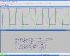
I've modified my circuit that I posted yesterday, and attached it here. The new circuit should output a programmed duty cycle from a square wave input, over a frequency range of at least 7 or 8 to 1. The waves at the top of the attachment are from yesterday's circuit, which has been reproduced in it's entirity with added components to correct the orginal circuit's lack of variable frequency performance. I have not simulated the whole circuit, and include it just as a design idea. You may of course take it, simulate it and make any changes you need to achieve your desired performance.
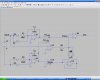
As before, U1 and U2 create linear ramps from the input signal, the output of U1 rising twice as fast as U2 due to the 2:1 ratio of the input resistors. The two ramp signals are added to form the green signal at the node labled "Ramp." Added to the circtuit is the peak detector labled "Peak" ( U5 ) which captures the peak value of the ramp outptu by U2. A signal is generated at U2 which is the inverted input signal and clamped at +/- value of the peak detector. As the complex "Ramp" signal rises at the input of U4, the output of the amp goes high as the ramp rises above the value captured by the "peak" block. Then, on the negative going portion of "Ramp" the output changes again as the input crosses the inverse of the "peak" value. Because the ramp is falling twice as fast as it rised, the output of U4 is active approximately 33% of the duty cycle. The block labled "Peak" can be made from the same opamps as the rest of the circuit. I have a schematic in the datasheet for LM324 Quad Opamp datasheet for it.
This circuit could be built to output a wave of programmable duty-cycle form a square wave input, by adjusting the ratio of R1 and R2. Back when people still designed electronic solutions, curcuit to convert between waveforms were common. It can be made from two Quad Opamp IC's and about a dozen descreete parts.
There remains some design work to do here. I can provide a diagram for the "Peak" block, but you would need to modify it some for the best performance. You would also need to manage the curcuit errors. It can be done, just a matter of how much effort and time you can put into it.
EDIT: U6 should be a unity-gain inverter. I've incorrectly showin it as a comparator. Also, I left out the 100nf capacitors on U1 and U2 that make them integrators. Refer to the original circuit for the placement of the capacitors.
Oops, one more thing. There should be a resistor of about 10k between the output of U2 and the point where the clamping diodes attach.
Attachments
Last edited:
")
