Continue to Site

Welcome to our site!

Electro Tech is an online community (with over 170,000 members) who enjoy talking about and building electronic circuits, projects and gadgets. To participate you need to register. Registration is free. Click here to register now.

  • Welcome to our site! Electro Tech is an online community (with over 170,000 members) who enjoy talking about and building electronic circuits, projects and gadgets. To participate you need to register. Registration is free. Click here to register now.

making a toggle switch help

Status
Not open for further replies.

vikas1974

New Member
Hi all

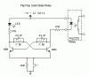
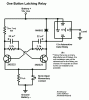
I wish to make toggle switch which will operate a 12 v relay ! When i press the button the relay gets in ON position and when i again press the same button the relay goes OFF . I am new in this field but I can make circuit if i know the components required. do i need 555-IC or 4011-IC. Please help me soon .


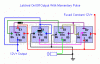
I also wanna design a simple Infra Red remote operated light . Please let me know the circuit diagram !
 
Try the diagram below. When the button is closed, the transistor sees +12 volts. When the button is open, the grounded 10K resistor allows the transistor to see 0v. The capacitor is there for debouncing, otherwise you will get glitches when the button opens and closes.

The 10K resistor going into the base of the transistor is there to limit the current. The transistor's emitter is grounded. One terminal of the relay is connected to +12v, the other is connected to the transistor's collector. There is a diode across the relay's terminals which may look like its backward. This is intentional. When the relay is on and working normally, the diode is not. But as soon as the button is released and the transistor turned off, the relay tries to keep the current going, and could fry the transistor. The diode allows the current to cycle around and dissipate while protecting the transistor.

The transistor is a general purpose NPN. The value of the small capacitor isn't too important. You could use another diode part number too.

As for the IR remote, I'm not too sure about that.
 

Attachments

  • relay.png
    relay.png
    3.3 KB · Views: 757
I'm not sure if thats quite what he's after, can't entirely figure out what that does, but it looks like its only on when you hold that button. I think he needs an S-R latch circuit, but where it can be latched and reset from the same button. Thus, an S-R latch made from lagic gates, with a 2 bit counter and some kind of output stage to drive the coil should work. I'll try and draw a scematic if you need one.
 
Hi

the normal way of doing this is to use a J-K flip flop, there are plenty of debounced designs on the web

Best of Luck

Ed
 
try this... pin 14 and 16 connected to v++ and pin 8 connected to ground

if you have any more questions then feel free to ask. if you need to send some pulses out of those output pins then send the signal in from pin 14

the chip takes maximup voltage of 9V (this is safe power) search for datasheet for more info
 

Attachments

  • fliper.jpg
    482.1 KB · Views: 708
Dr.EM said:
it looks like its only on when you hold that button.
Ah. Yes. I forgot to read the message twice and make sure I'm solving the right problem. I just loaded up MS-Paint and went straight to work. :eek: 
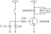
Oh well I got most of it anyway hehe.
 
vikas1974 said:
..... toggle switch ..... When i press the button .....
A toggle switch has a short operating lever on it.

This should do what you want.

The circuit round the two inverters is well known but owes its exposure in these forums to Audioguru.
 

Attachments

  • altrelay.gif
    altrelay.gif
    4.5 KB · Views: 671
Thanks David, I couldn't find it. :lol:

BTW, your diodes are backwards. :(
 

Attachments

  • altrelay_corrected.gif
    altrelay_corrected.gif
    4.8 KB · Views: 651
Dont' you just hate it when that happens .....

Thank you.
 

Attachments

  • diocor.gif
    diocor.gif
    2.2 KB · Views: 607
David Bridgen said:
Dont' you just hate it when that happens .....
Hi David, which one do you think will blow-up 1st, the diode or the transistor? I think the transistor will blow to protect the backwards diode. :lol:
 
Toggle relay one button.
 

Attachments

  • flip_flop_solid_state_relay.gif
    flip_flop_solid_state_relay.gif
    3.6 KB · Views: 721
  • latchonoffsp.gif
    latchonoffsp.gif
    11.9 KB · Views: 614
  • on_off_push_button_relay.gif
    on_off_push_button_relay.gif
    3 KB · Views: 612
More?
 

Attachments

  • toggle_ff_relay.gif
    toggle_ff_relay.gif
    3.7 KB · Views: 650
  • one_button_relay.gif
    one_button_relay.gif
    5.7 KB · Views: 785
  • one_button_latch_relay.gif
    one_button_latch_relay.gif
    15.8 KB · Views: 2,138
Status
Not open for further replies.

Latest threads

New Articles From Microcontroller Tips

Back
Top