Continue to Site

Welcome to our site!

Electro Tech is an online community (with over 170,000 members) who enjoy talking about and building electronic circuits, projects and gadgets. To participate you need to register. Registration is free. Click here to register now.

  • Welcome to our site! Electro Tech is an online community (with over 170,000 members) who enjoy talking about and building electronic circuits, projects and gadgets. To participate you need to register. Registration is free. Click here to register now.

Making a small 12v DC converter to 3.8v (HOW??? HELP!!!)

Status
Not open for further replies.

Johnnyairtime

New Member
Dear sirs (anyone at this point)

I've been hammering away at an answer to a question you maybe able to help with. I'm definitely not an elect. engineer, a technical engineer or anything relative to what you need to be to figure this out... so please bare with my ignorance.

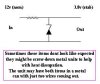
I have a GPS unit the works on 3.8v (this is what Magellan technical told me) I currently use a premanufactured adapter supplied by the Magellan manufacturer.... it plugs into a 12v source and converts it to the 3.8v via a 'black box' inline with the cable. My problem is the continuity between the 12v source connection and the GPS's 3.8v connection is broken. And I believe it's breaking continuity due to vibration on a dirt bike. More than likely in the little 'black box'... that isn't so little.

I'm just short of breaking that box open... and trying to isolate the problem. Even if I opened it... I wouldn't be too sure how to fix it or how to diagnose a problem unless I saw a cold solder or broken connection.

Is there an easier means (using resistors) maybe sealing something in a non conductive silicone for vibration control??? I'm sure they may be using resistors or some kind of transformer (converter) now....

HELP!?!?
Can I be enlightened to make a stronger more solid converter box??!!!

If you can help... or would like to be paid to make me a real durable cable end to end (Using Magellan's connector for the GPS)....

Please send me mail at; John@johnnyairtime.net
I am eager to get this resolved.
 
Hi,

Since the unit is not working,
break it open carefully,
and describe the contents as best you can.

It is probably a zener and resistor.

Someone will guide you to fixing it up,
the zener is unlikely to be damaged,
and then you could seal it up with some sort
of silicone putty or similar, to hold it all
firmly and keep any moisture out.
Using Araldite or epoxy glue would make it
hard to get back into it if theres a problem.

If its just the end connection to the unit from
the cable, as you think, then you will probably
see the problem when you uncover it.

John :)
 
I think I'll spend some time pulling it apart tonight....
Thanks for your help so far.

Also... I got this reply in personal email from another man named Al.
See if it makes sense too;

Hi John,

Well, this is a tricky question. It is unlikely that the converter is just a
resistor. The reason is that a resistor in series drops a varying amount of
voltage depending on the load. Also as the source voltage moves (which it
will in a car) the output voltage moves.

There are two typical ways that you would design a converter like this. One
way is to use a linear regulator. A linear regulator dumps extra voltage out
as heat. They make linear regulator chips that are very easy to use. The
downside is they waste power and they generate heat. The up side is they are
cheap and easy. In fact, it is possible to make linear regulators with Zener
diodes and other inexpensive parts although an IC version will perform
better.

The other way to go is a switching regulator. These are complex circuits
(although you can get them done up on a chip or chip-like package now).
Basically they store energy and release it as necessary to produce a
voltage. These can be highly efficient and generate little if any heat. But
they are complicated and generate a certain amount of noise not present in a
linear regulator.

None of these are probably going to be easy to make more rugged than the one
you have bought.

Presuming you are operating from an engine with an alternator, I wouldn't
worry about efficiency, and heat is probably not an issue. If I were
building something like this I'd consider an LM317 regulator with a few
external components. After it was built and working, you could encase it in
flexane or some other potting material. But I'd guess you would have just as
much luck buying a ready-made cable, taking it apart, and potting it
instead.

One other question to ask yourself. Are you sure this is the problem? Could
it be the cigarette lighter plug is intermittent? Could it be an
intermittent fuse? Or a loose connector to the GPS
?
 
Hi Johnnyairtime,

Yes, 'Al' is quite correct, it is unlikely to be just a resistor.
and he is also correct that the various voltage stabilising chips
would do it quite well.

However on motor-bikes the norm is to go for the simplest and
most basic method, and for this the simplest is a resistor and a
zener diode.

Yes, it is not power efficient, but my guess is that the GPS unit
is a pretty light load anyway.

I have included a diagram of the sort of thing i would expect to
find doing this job. When you get into it, if it looks like this
is not the arrangement, then please describe what you find, and
someone, or me, or Al, will hopefully know what it is.

I expect you to find a loose or poor connection, with any luck
you will not need to be concerned with the unit, other than that.

Best of luck with it, John :)
 

Attachments

  • Dropper_Zener.jpg
    Dropper_Zener.jpg
    13.3 KB · Views: 1,018
Well, I didn't get to break it open last night... but I can also add that the whole cable assembly is only $11 so it can't be too eloborate.

And again, thank you both for your help so far.
I'm even more eager to look into this "black box"... :)
 
converter

You can get universal converters with adjustable voltage for cd players radar detectors exc. They plug right into the lighter in a car, do a little splicing, positive to positive negative to negative make sure of this.
I am not quite sure but i think the one i had label 3.8 volts.

are you possitive it is just 3.8 volts in or a couple different voltages all the way up to 3.8
hope you get it worked out
 
Status
Not open for further replies.

Latest threads

New Articles From Microcontroller Tips

Back
Top