Continue to Site

Welcome to our site!

Electro Tech is an online community (with over 170,000 members) who enjoy talking about and building electronic circuits, projects and gadgets. To participate you need to register. Registration is free. Click here to register now.

  • Welcome to our site! Electro Tech is an online community (with over 170,000 members) who enjoy talking about and building electronic circuits, projects and gadgets. To participate you need to register. Registration is free. Click here to register now.

Making a Bluetooth adapter for a Car Phone from the 90's

Call waiting can be confusing, even when it's working perfectly with a high quality display of a modern touch-screen phone that presents multiple options with descriptive labels, and can clearly show the status of multiple calls.

IMG_7224.PNG


Try to implement support for call waiting on a vintage car phone with physical buttons never intended to intuitively support this functionality, and a display that can only show 2 lines of 7 characters each, while working with limited information about call state from the Bluetooth Hands-Free profile, and it gets way more confusing.

First, I'll describe the possible call statuses that can be reported by the Bluetooth module:
  • IDLE: Not in a call, nothing happening.
  • VOICE_DIAL: Not quite sure, because I'm not using this. I think when the phone's voice assistant is activated? (e.g., Siri for iPhone)
  • INCOMING: Someone is calling you. You can answer the call, or reject it.
  • OUTGOING: You initiated a call, and the recipient has not answered yet.
  • ACTIVE: You're actively in a call.
  • ACTIVE_WITH_CALL_WAITING: You're actively in a call, and someone else is calling you. This is when you see the terrifying options pictured above.
  • ACTIVE_WITH_HOLD: You're actively in a call, and another call is on hold.
The Bluetooth module sends an event over UART to the MCU whenever this status changes.

There are also many commands supported by Bluetooth HFP that affect the call status. There are raw AT commands for each of these, and the Bluetooth module exposes these as supported UART commands:
  • Place an outgoing call to a specified number.
  • Answer an incoming call.
  • Reject an incoming call.
  • End all calls.
  • End the active call and accept the call waiting.
  • Reject the call waiting call (send it to voicemail).
  • Place the active call on hold and accept the call waiting.
  • Swap the active call and on-hold call
    • If only one call in progress, then it toggles that call between active and on hold.
    • NOTE: There is no call status that corresponds to this idea of "only a single call, and it's on hold". There's no way detect this status or transition in status via the call status event. It's always simply "ACTIVE" regardless of whether the call is on hold or not.
  • End all calls except for the active call.
  • End the active call and swap to the on-hold call.
  • Plus more that I'm not worrying about.

The only buttons on the car phone that can reasonably relate to any of these actions are:
  • END
  • SEND
  • FCN (for modified/alternate action)
keypad.png


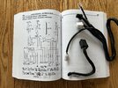
I started with evaluating the original behavior of these buttons according to the car phone's owner's manual:
  • END:
    • Rejects an incoming call.
    • Ends an active call.
  • SEND:
    • Answers an incoming call.
    • Sends a "flash" request while in an active call.
      • NOTE: Equivalent to to quickly pressing the "hook" button on older analog land-line phones, which is how call-waiting calls were answered/swapped when call waiting was introduced to land-lines.
  • FCN + SEND:
    • While in an active call, sends the current digits on the screen as DTMF tones.
And I tried to come up with a way to make use of these buttons to provide all the necessary call waiting functionality while retaining consistency with the original basic functionality of these buttons. I decided on the following basic core rules:
  • END always ends the currently active call.
  • SEND answers incoming calls, and can swap between multiple calls (but never ends any calls).
  • FCN + SEND is off limits for call status management because it is already used for a specific different purpose.
  • Avoid making use of other arbitrary buttons on the handset, because it would never be intuitive that RCL, CLR, or STO (for example) should be pressed when dealing with answering/ending/swapping calls.
But following these simple rules leaves a gap in functionality:
  • When there's a call waiting, SEND obviously should answer it (placing the active call on hold), END should end the active call (while accepting the call waiting), but how do we reject the call waiting and stay on the active call?
  • When in an active call with another call on hold, SEND should swap the calls, END should end the active call and swap the on-hold call to active, but how do we end the on-hold call and stay on the active call?
Conveniently, the gap in both cases has a consistency: it involves getting rid of the "other" call that is not the active call. I decided that FCN + END was a reasonable button sequence for an "alternate" end/reject functionality (affects the "other" call instead of the active call).

I think this results in a fairly easy-to-remember pattern of what the buttons do in all cases (even when call waiting is involved):
  • SEND:
    • If there's an incoming call of any kind, it will accept that call.
      • If a call was already active, then that call is placed on hold.
    • If there is no incoming call of any kind, then it will swap the "active" and "on-hold" call.
      • If there is only one call, it toggles it between "active" and "on-hold".
  • END:
    • Ends the active call.
      • If there's an on-hold or waiting call, then that call will become active.
  • FCN + END:
    • Ends the "other" call (on-hold or waiting).
    • Irrelevant and does nothing if there is no "other" call.
The only ambiguity is that it might be intuitive to think that END would reject an incoming call waiting while already on an active call. There's two competing and incompatible possible assumptions about what the END button should do in this case, because there is both an incoming call that can be rejected and an active call that can be ended. I had to pick one for the call waiting situation, and I think my decision is the more consistent of the two (because it allows FCN + END to have a consistent meaning).

So that's one tough job done: simply understanding the possible call states and actions that can be taken in each state, and deciding how to use the buttons to perform those actions.

To be continued...
 
Last edited:
Next up on the Call Waiting journey is deciding how to present information to the user about the status of the call.


Simple incoming call (status: INCOMING)

incoming.gif


An incoming call interrupts anything the user is doing and does not allow the user to do anything aside from answer (SEND) or reject (END) the call, and adjust the ringer volume (up/down arrow buttons on side of handset).

In a normal single call (status: ACTIVE)​

While in a normal single active call, we have a "talk time" timer by default and the "IN USE" indicator is on. The user is also free to perform most operations on the phone (adjust settings, recall numbers from the contact list, etc.). But any time they return to the "home" screen, and have no numeric input entered on the screen, the talk timer displays again:

active.gif


The call can be ended (END), or put on/off hold (SEND).

Incoming call waiting (status: ACTIVE_WITH_CALL_WAITING)​

When in an active call, and another call comes in (call waiting), I decided I should remain consistent: interrupt anything the user is doing and show the "incoming call" screen. The differences in this call state are that the "IN USE" indicator will be on due to the current active call, the current active call's audio will still be active (instead of a ringer), and the volume level of the call audio is adjustable (instead of ringer volume):

active_with_waiting.gif


The audio from the paired cell phone conveniently already includes the beep notifications that there's another call incoming. In this state, the user is again limited to making a decision on how to handle this incoming call waiting: Place the active call on hold and answer the call waiting (SEND), end the active call and answer the call waiting (END), or remain on the active call and reject the call waiting (FCN + END).

In a call with another call on hold (status: ACTIVE_WITH_HOLD)​

When in an active call with another call on hold, it is much like being in a normal single active call, but I make the "IN USE" indicator flash on/off as a reminder that there is another call on hold.:

active_with_hold.gif


The behavior of the SEND/END buttons is also adjusted for this call state: you can swap the active/hold calls (SEND), end the active call and activate the hold call (END), or end the hold call while remaining in the active call (FCN + END).

Seems pretty easy so far? It's about to get messy...
 
While testing all the different Call Waiting stuff, I've encountered some awkward situations, and I don't think there's anything I can do about it. It all comes back to the concept of being in a single call, but it is on hold: there is no distinct call status for this situation, and no event from the Bluetooth module to indicate changes between hold and active, because it's all the same call status.

For example:
  1. Get into a call. Status = ACTIVE.
  2. Answer a call waiting. Status = ACTIVE_WITH_HOLD
  3. The other person on the active call hangs up. Status = ACTIVE, but the other call remains on hold. User must press SEND to take the call off hold.

IMG_0370.JPG


In this situation, I have no easy way to detect that the "ACTIVE" call is actually on hold. If I could, I would display something on the screen to indicate that a call is on hold.

The only event or status change that is accompanied with this situation is that the SCO connection (voice audio connection) for the first call disconnects when it ends, but the SCO connection does not reconnect for the on-hold call. I can't make many assumptions based on this, because the SCO connection can also be disconnected when you transfer audio from the Bluetooth device back to the cell phone. But I may be able to use this SCO connect/disconnect event as a trigger to query the call list (AT+CLCC command I used to get Caller ID info), then I can parse the responses to determine if there's only one call, and if it is on hold. Unfortunately, the AT+CLCC command does not immediately report correct status if executed right after the SCO connect/disconnect. It takes some time. I have to add an arbitrary delay to get correct results, which is unreliable. I really wish there was a distinct "ON_HOLD" call status.

Then there's a super obnoxious bug that I think is an iPhone-specific bug:
  1. Get into a call. Status = ACTIVE.
  2. Answer a call waiting. Status = ACTIVE_WITH_HOLD
  3. Press END to end the active call and swap to the hold call.
    1. Expected: status = ACTIVE, and the call that was on hold is now active.
    2. Actual: status = ACTIVE, but the cell phone shows that the ended call is still active for several seconds. Then the active call finally ends, but the on-hold call remains on hold.
If between steps 2 and 3, I press SEND to swap calls, then press SEND to swap calls again, I'm right back to the same situation (second call is active, first call is on hold). Pressing END behaves exactly as expected now.

I initially suspected a bug in the Bluetooth module's implementation of its "end call and swap hold call" UART command, so I found the raw AT command to do the same and tried sending the raw AT command through the BT module to the cell phone. Same behavior.

I hate Call Waiting...
 
Now it's time for my adventures in battery level detection/reporting.

The original behavior of the car phone is that you display the current battery level in the form of 1-5 dashes:

1651894071007.png


There's also low battery indication:
1651893928873.png


My original attempt at re-implementing this behavior was to use an ADC input on my MCU to measure the voltage of the power supply to the handset. I was able to roughly convert this voltage reading to a battery level similar to the original phone, but I could never quite get it right. The biggest problem was that I could not accurately determine when the phone was entering into "low battery mode". I want to be able to accurately detect this so I can produce the low battery indication and warn the user that the phone may turn off soon (remember: I'm using the original transceiver as my power supply for both the handset and my circuit, and its decision to power down is beyond my control).

So I took a different approach now. I have plenty of UART modules on my MCU, so why not use another to communicate directly with the transceiver using UART commands?

Here's my rough ASCII art sketch of all the UART communications on my circuit now:

|M| <==UART1==> [Handset]
|C| <==UART2==> [Bluetooth Module]
|U| ---UART3--> [Console logging to PC]
| | <==UART4==> [Transceiver]


Fetching the Battery Level​


To read the battery level from the transceiver, I can simulate the button press sequence from the handset to the transceiver to cause the transceiver to display the battery level, then monitor the resulting UART commands that the transceiver tries to send the handset and count how many dashes (-) it wants to print to the display. I know when the transceiver is done printing the battery level when I have received at least one dash, and then receive the command to enable the text display. NOTE: none of these commands from the transceiver actually make it to the handset. Only my MCU is communicating with the transceiver.

My initial implementation was to do this on-demand when the user tries to view the battery level on the real handset (same FCN / * / 5 button sequence). However, there was quite a delay because of the slow 800 baud data speed of the handset/transceiver UART communication. This on-demand fetching also won't be sufficient for sending the battery level to the paired phone for display of the Bluetooth device's battery level.

So I reworked it to periodically fetch the battery level from the transceiver always (every minute). So I always have a battery level value ready to display immediately. I can also send the battery level over Bluetooth any time the new battery level is different from the previous level. There's some additional details about the timing of the first battery level fetch to ensure the transceiver is ready to respond to button presses, timing out if I don't get a battery level response from the transceiver, simulating the CLR button press to try to recover (return the transceiver's state back to being on the "home" screen ready to handle the button sequence again).

IMG_E7228.JPG


I still trigger a fetch of battery level to happen when the user attempts to view the battery level. This "hybrid" approach allows me to immediately display a battery level that is correct within the last minute, but then also possibly update the display to be more correct value as of right now when the transceiver finishes responding in about 1.5 seconds.

Detecting "Low Battery" Condition​

When the battery is low, the transceiver does a few things:
  • Starts flashing the PWR indicator on/off about once per second.
  • Produces a beep about once every 20 seconds.
  • Displays "LOW BATTERY" on the screen when the user is at the "home" screen with no digits typed.
When the low battery condition ends (due to being plugged into an external power supply), the PWR indicator stops flashing (remains on), and the "LOW BATTERY" message is cleared from the screen.

The flashing PWR indicator is the the simplest thing for me to detect. The transceiver flashes the indicator by turning it on and off repeatedly. I can detect the PWR indicator/on off commands. When I receive a PWR "off" command, I know that the battery is low. If some amount of time passes after receiving the PWR "on" command, and I have not yet received another PWR "off" command, then I know the battery is no longer low.

With this information, I can now maintain a "low battery" status in code and handle transitions in this status to reimplement all the original low battery indication behavior.

I also trigger an immediate battery level fetch any time the low battery status changes to guarantee that the battery level value I have in memory is in sync.


Coming next: communicating battery levels over Bluetooth...
 
Last edited:
The Bluetooth module supports a UART command to send a battery level to the paired phone, which the phone can display in various ways

IMG_7256.PNG


IMG_7255.PNG


I was already making use of this from back when I was trying to calculate a battery level value from the voltage of the power supply. But now that I have an accurate reading of the exact battery level from the transceiver, I started paying more attention to the reported battery level on the paired cell phone and noticed it didn't seem to correlate very well with the battery level I was presenting on the car phone's handset.

The UART command for reporting battery level uses a percentage value ranging from 0-100. The battery level I receive from the transceiver is a value ranging from 1-5 (number of dashes displayed on the screen). So a simple multiplication by 20 should produce battery percentages of 20, 40, 60, 80, or 100. But I sometimes saw a value of 10% or 70% presented on my cell phone.

So I temporarily adjusted some code to send every battery level from 0-100 (2 second pause between each command) while also logging to the console. I watched the console output and the battery voltage presented on my cell phone to discover the following relationship between reported battery level and presented battery percentage:

Reporting 0-29 presents as 10%.
Reporting 30-59 presents as 40%.
Reporting 60-89 presents as 70%.
Reporting 90-100 presents as 100%.

Not very good granularity of possible battery levels. As far as I can tell, this is a problem with my phone's handling of the standard command for reporting battery level over Bluetooth HFP (I tried sending the raw AT command for this and saw the same results).

After spending some time Googling, I found that there are some common proprietary AT commands for reporting battery level that existed before an official/standard command was added in HFP version 1.7. One of these commands is was introduced by Apple, originally for iPhone accessories, but is also supposedly handled by Android phones for compatibility: "+IPHONEACCEV"

I have an iPhone, so I decided to use the iPhone-specific command. It accepts a battery level value in the range of 0-9, which maps to presented percentages ranging from 10-100%, in 10% increments. So I convert my transceiver battery level (1-5) to a value for this command as follows:

[IPHONEACCEV value] = ([transceiver batt level] x 2) - 1

This produces the originally intended result of 20%, 40%, 60%, 80%, or 100% displayed on the cell phone.

If the battery is "low", the transceiver still reports back a battery level of 1, so I added a special case to send the battery level as 0 (10%) when the battery is "low" to create a distinction in displayed battery percentage on the cell phone.
 
The final piece of the battery-level reporting puzzle is to view the paired cell phone's battery level from the car phone's handset.

The Bluetooth module sends 2 UART events to the MCU related to the cell phone's battery level:
  1. Max battery level: specifies the integer value that represents 100% battery level.
    • Event sent after connecting to the cell phone.
  2. Current battery level: an integer from 0 to [max battery level]
    • Event sent after sending [max battery level] event, then any time the battery level changes.
Practically, the max battery level will probably always be 5, because the Bluetooth HFP specification says that the battery level indicator value has a valid range of 0-5. But I still wrote my code to account for any possible max battery level just in case:

[display level] = ([reported level] x 5) / [max level]

However, this would always round down due to integer math. To achieve "normal" rounding (round to nearest integer), I added a bit more complexity:

[display level] = ((([reported level] x (5 x 2)) / [max level]) + 1) / 2

But it doesn't matter in practice, because the max is always 5, which is exactly the max of the range I can present.

NOTE: Cell phone signal strength is reported with the same approach, and I do a similar calculation to map the reported signal strength to the range of up to 6 bars supported on the car phone handset display. The rounding actually does matter here, because the practical consistent max signal strength reported over Bluetooth is 5.

I enhanced my battery level display feature on the car phone handset so that you can toggle between viewing the car phone battery level and the paired cell phone battery level by pressing the FCN button.

Car phone battery level:

IMG_E7228.JPG


Paired cell phone battery level:

IMG_E7229.JPG


I'm not entirely happy with the label "CELLBAT" for the paired cell phone battery level, but it's hard to come up with a good clear label that is 7 characters or less. I'm open to suggestions :).
 
Last edited:
Would you be willing to sell a board for someone else to do the same?

Additionally, I want to do something similar with an analog flip phone from 94, but I’m pretty sure that’s not doable with the size limitations. What you you suggest for that, just the Bluetooth headset approach?
 
Would you be willing to sell a board for someone else to do the same?

It's just a sloppy prototype on a couple breadboards right now. I'm not sure I'll ever get to the point of creating a PCB. I'll probably move the circuit to a soldered prototype board and call it good enough.

I'll eventually post circuit diagrams, config files, source code, precompiled binaries, etc., that you could use to replicate what I've done. But I'm not ready to do that. It's still too sloppy and I'd be embarrassed to share my code as it sits now.

Additionally, I want to do something similar with an analog flip phone from 94, but I’m pretty sure that’s not doable with the size limitations. What you you suggest for that, just the Bluetooth headset approach?

My approach would not work for a flip phone or any other kind of single-piece phone. My approach relies on being able to communicate directly with the handset, which is a completely separate component with digital communications that were easy to intercept and reverse-engineer.

I don't have any suggestions for how to modify a flip phone to work as a bluetooth headset in a similar way.
 
  • Like
Reactions: MKS
Hi UselessPickes, I found this project so interesting. In my 40s now, I remember the installed AMPS 3-watt car phones. My single mom had one. In my teens I worked a paper route to save money specifically to have a Motorola phone installed in her car. But dare I play with the phone and accidentally make a call I think my fingers would have been cut off. These were the time of $0.40+ per minute calls - the phone was strictly for emergencies. It may have been used 2-3 times that I can remember. All that said, I've played with the idea of bringing that phone (I still have it, a Motorola AC-250) back to life. I briefly looked into the Raspberry Pi implementation of an AMPS tower. I didn't see code available to actually route the call to the public phone network and I worried (maybe unfounded) about the full 3 watt of power if I were ever able to get the project up and running. But when I read about you sniffing and backward engineering what traffic between the transceiver and handset I smiled, I never thought of that approach.

Curious if you actually may clean up your project and publish it - I would be all over reading and learning more. Also, wondering, did you ever "sniff" other phone handsets? Any idea if DiamondTel/Mit and other manufactures all used similar (or the same) methods for the handsets? Or is everyone completely different? Essentially if I took your work and tried to replicate it, would I be starting from scratch trying it with my Motorola?

Thanks for putting this out there. Even if I don't ever do anything with it I learned a lot.
 
Last edited:
Hi UselessPickes, I found this project so interesting. In my 40s now, I remember the installed AMPS 3-watt car phones. My single mom had one. In my teens I worked a paper route to save money specifically to have a Motorola phone installed in her car. But dare I play with the phone and accidentally make a call I think my fingers would have been cut off. These were the time of $0.40+ per minute calls - the phone was strictly for emergencies. It may have been used 2-3 times that I can remember. All that said, I've played with the idea of bringing that phone (I still have it, a Motorola AC-250) back to life.

Thanks for sharing the story! I never had any personal experience with car phones back in the day (don't recall ever even seeing one back then).

I briefly looked into the Raspberry Pi implementation of an AMPS tower.

My original idea was to similarly try to figure out how to build an implementation of an AMPS base station that would connect directly to the antenna port of the transceiver, and interface with a Bluetooth module. The electronics involved for that was just way beyond my understanding, and it would have actually been more limiting in some ways than the approach I am going with now. The communication to/from the car phone would be restricted by the AMPS protocol.

My approach gave me a nice blend of replicated originality (I re-implemented much of the original phone handset behavior as exactly as I could), but with adjustments/improvements/additions as necessary to interface with Bluetooth as conveniently as possible... plus some extras like custom ringtones, caller ID, and call waiting :). It's more of a "resto-mod"

Curious if you actually may clean up your project and publish it - I would be all over reading and learning more.
Definitely. I'll probably start making progress on that this winter. I'll have to start with just publishing what I have so far with a major caveat that it's still a work-in-progress (so don't judge me for the sloppy code).

I haven't touched this project all summer because of summer fun and car projects using up all of my free time.

Also, wondering, did you ever "sniff" other phone handsets? Any idea if DiamondTel/Mit and other manufactures all used similar (or the same) methods for the handsets? Or is everyone completely different? Essentially if I took your work and tried to replicate it, would I be starting from scratch trying it with my Motorola?
I know two things for sure:
  1. The Mitsubishi Model 1500 handset is interchangeable with the DiamondTel Model 92 handset. I have tested with both. I also was told by someone that previously sold/installed these phones that those two models of phones were compatible with each other.
  2. Someone showed me a pinout of another brand/model of car phone handset (don't remember what it was), and it was quite different.
I haven't tested any other handsets.

It's possible that some other Mitsubishi models may be similarly compatible. I suspect that the interface is proprietary to Mitsubishi and probably changed throughout the years even within Mitsubishi. There is one UART command I discovered that causes the handset to respond back with some value. I never figured out what it means. It may be some kind of handset model/protocol/version identifier that could hypothetically be used to add support for additional Mitsubishi handsets that use the same overall interface, but different command sets? FWIW, both the Model 92 and Model 1500 handsets respond the same as each other to this command.

For your Motorola, you'd probably be starting from scratch reverse engineering how to interface with that handset. Everything in my circuit and code that is specific to interfacing with the handset would need to be reworked to interface with your handset.
 
(TL;DR: I programmed some games on the phone as motivation to help organize code better. Videos at the end of this post)

Now that Summer is over and the phone has been pulled out of the car for Winter storage, I'm back to working on this project. I'm really procrastinating on building a more robust soldered prototype of the hardware, so I'm working on the software instead (because I'm a software engineer and hardware/electronics is mildly terrifying to me).

Much of the software is a disorganized mess that was thrown together and hacked just to figure out how to get things working. Now that I have a majority of functionality "working" and I have solved many technical challenges, it's time to start cleaning things up to improve reliability of existing functionality and improve my ability to continue adding/adjusting functionality (and to reduce embarrassment when publish the code).

Most of the functionality of the phone is a giant mess in a single file that has become very confusing. In order to fix this, I had to come up some patterns to follow that allow me to break out substantial pieces of functionality into separate smaller files, with a way for handset events and timer events to be "directed" to the currently "active" piece of functionality, with a way for that piece of functionality to "return" control back to the "parent process"... but with the ability for certain important things (like an incoming call) to still occur.

I won't get into the technical details of the pattern I settled on, but it basically allows me to organize the project much better AND reuse pieces of functionality from multiple contexts .

And what's the best way to test out my new patterns? How about developing a game! While playing a game, the game needs to be receiving all all the relevant handset and timer events, and a main "task" function for the game needs to be called from the primary task loop of the MCU program. It was also a great way to test reusing the volume adjustment functionality from within the game in such a way that control is returned back from volume adjustment to the game.

Many months ago, I had talked about the general idea of making a game on the phone. One of my kids jokingly suggested the "Snake" game. We laughed about how ridiculous that game would be on only a 7x2 grid, and then I knew it had to be done. So I present to you the most cramped version of "Snake", running on a phone that was released 5 years before Nokia first introduced the world to mobile gaming on their Nokia 6110 in 1997 (with "Snake" being the most well-known of the 3 games on that phone).


The faster levels are quite challenging, but I am able to beat them when not also trying to record a video :).
I excitedly showed this game to my wife, who promptly got frustrated and hated the game. She's not a gamer and just doesn't do well with anything requiring quick reaction and pressing of correct buttons at the right time. So in a quest for a more positive response to my creation, I decided I needed to develop a more casual slow-paced puzzle game that fits her playing style.

So now I present to you what is likely the smallest version of the "Memory" pair-matching game, which was also one of the 3 original mobile games introduced by Nokia:


So now I have 2 out of 3 of the OG Nokia mobile games implemented, using up 2 of the 3 "preset" buttons on the handset to access the games. I think it's quite obvious what needs to be done next. I have no choice but to complete the collection. Unfortunately, I don't know much about the "Logic" game from Nokia. I need to dig up some descriptions, photos, and/or videos of this game to find out how it's supposed to work. But this is now my top priority with this project. Anything to further procrastinate cleaning up the messiest parts of my code, or working on hardware :D

(UPDATE: I have now figured out that the Nokia "Logic" game is basically "Mastermind")
 
Last edited:
My son challenged me to make another game the phone: Tetris! Much like the “snake” game I made previously, we first laughed about how ridiculous Tetris would be on a 7x2 playfield, but then started talking through how it could actually work and realized that it really could work… but with some alterations (aside from the obvious smaller playfield).


This time I went all out with multiple sound effects that are more complex than simple single beeps, and background music! You can’t have Tetris without that iconic music. I adapted the music from a sheet music arrangement I found for an accordion solo :D

The pieces have to fall sideways instead of down. The pieces can’t be more than 2x2 in size. And a minimum of 2 lines must be filled to clear out, otherwise individual pieces can partially or fully clear themselves out when they land. To increase the challenge, the pieces spawn in a variety of orientations, instead of always spawning in the same predictable orientation. It actually gets quite difficult on the higher levels when the pieces drop faster. The level-dependent scoring and automatic advancement through the levels is a simplified version of how the NES version of the game works.

You can really see the limitation of the display’s update speed when completed lines are flashing before they disappear. I had to optimize how I update the display as pieces move to minimize the writes to the display, and strategically choose what order to update individual “cells” of the display to get the best illusion of smooth-ish motion.

This might be the peak and crowning achievement of my mobile game development career. It will be tough to think of a more interesting game that could be adapted to work surprisingly well on such a limited device.

BTW - I decided not to try to make the Nokia "Logic" game because there's just not enough room on the display to present all the necessary info in a usable way, plus Tetris is a much more interesting game to occupy the spot of my 3rd and final "game button" on the handset.
 
Last edited:
I finally started working on publishing this project on GitHub: https://github.com/UselessPickles/diamondtel-m92-bluetooth

I'm not proud of my microcontroller code yet, but now it's backed up with version control so I can manage changes better from now on. There's still a lot of work to do:
  • Circuit diagrams, parts list, and datasheets for all components in the circuit.
  • Overview of how all the components of the circuit interact with each other.
  • Technical details about the phone.
  • More friendly information about how to load the configuration onto the BM62 Bluetooth Module.
  • Document overall architecture and patterns used in the MCU source code.
  • Tons of cleanup and reorganization of the MCU source code.
 
My GitHub repo has a lot of updates:
  • Diagrams of the basic design of the project, and major components of the circuit.
  • Compilation of all the technical details about the car phone handset wired connections, UART commands/events, etc.
  • Summaries of all the peripherals and I/O pins used by the microcontroller software.
  • List/description of all the major components used in the circuit, and copies of their datasheets.
I still have a lot more to do with describing the architecture of the microcontroller code, and creating detailed circuit diagrams. But I think I first want to finalize some details on the breadboard and transfer to a soldered prototype board before I get deep into circuit diagrams. I'd like to add in some dip switches and pin headers that would allow for easy in-circuit reconfiguration of the Bluetooth module (it currently requires that I partially disconnect the Bluetooth module from the rest of the circuit to prevent the MCU from interfering)

Here's a couple diagrams for your viewing pleasure:

basic_component_diagram.png


circuit_component_diagram.drawio.png
 
Last edited:
I've always wondered how exactly the phone originally behaved when it really has service, when it's in a call, etc., but I've only been able to make educated guesses and assumptions based on limited descriptions of functionality in the owner's manual.

Wonder no more! I recently learned about the existence of "mobile service test" equipment that is used for development/testing/diagnosis of cell phones. After some searching, I found a used obsolete Wavetek/WWG/Acterna MMS-4305 Mobile Service Test Instrument that supports AMPS (the analog standard used by this phone) for just over $200 including shipping (the shipping itself was $110!).

Here's video demonstration:


I can't really find any information about this particular device (not even operating instructions), so I'm just stumbling through the menus and winging it. Some similar devices from other brands used to cost $10,000-$13,000 or more! That's around $20,000+, adjusted for inflation. I've heard that similar equipment for modern cell service testing is $100k+. All it takes to become affordable for hobbyists is to wait 20-30 years until the technology is long obsolete :D

Here's a video comparing the startup sequence and an incoming call between the original phone and my replica behavior/sounds for the Bluetooth adapter:


I've already learned about several details I had wrong:
  • The ringtone cadence is 1 second on, 3 seconds off. I previously guessed it to be 1.5 seconds on, 3.5 seconds off, based on nothing more than what "seemed to sound good". I fixed this already.
  • Adjusting volume is "silent" when sound is currently "playing" for the volume mode being adjusted (e.g., no volume button beeps when adjusting voice volume in a call, or adjusting ringer volume while the phone is ringing). I fixed this already.
  • The optional "warning beep" 10 seconds before every minute of talk time is ALWAYS played through the loud speaker, regardless of whether handset is on or off hook (e.g., even when voice audio is coming out the ear speaker), and the "TONE" volume level is always used. I incorrectly assumed that the beep should play through the same speaker as voice audio, and at the same volume level as voice audio. I fixed this already.
  • Immediately after placing a call, when the call timer is displayed, the current state of what number was previously entered is still retained. Pressing the CLR button hides the call timer and returns to the main number entry "screen" with the called number displayed. I'm currently clearing out the number input when a call starts, and I only show the call timer when the number input is blank.
  • The call time display can be toggled on/off with the CLR button when the number input is empty.
  • Some differences in how DTMF digits after a "pause" are processed (won't get into details here).

While I was splicing clips together for that video, I discovered that the sound of my replica ringtone had been wrong this entire time! The true ringtone was similar sounding, but "harsher". I already fixed it, but still included the wrong "smoother" sounding ringtone as an option (and included it at the end of the above video for comparison).

The true ringtone alternates between playing a dual tone and silence, repeating 20 times per second. The break in the sound creates the "harshness".

My incorrect "smooth" sound was produced by alternating between playing a high tone and a low tone (separately), repeating 20 times per second (using the same 2 tones as the true ringer). So the two tones still blend together a bit in your ear, and the alternating tones still creates the rapid "stuttering" effect in general, but it sounds "smoother" with a bit more distinction between the high and low tones.
 
Last edited:
Here’s a demo of service status indicators on my car phone synchronized with the actual service status of my modern cell phone. I recently learned that I can force my modern cell phone to connect to other networks (roaming), so I can actually test that I’m controlling the roaming indicator on the car phone correctly. Way better than trying to drive somewhere that my phone will naturally be forced to roam
1f606.png


I also added the status change beeps to match the original car phone behavior.

 
My car phone now supports voice dialing/commands (via Siri, Google Assistant)! I also improved the behavior of sending an outgoing call, and the call timer.


Previous behavior:
  • When sending an outgoing call, I would clear out the number input and simply display "CALLING" on the screen.
  • When in a call, the call timer would only display any time the number input is empty (which is true initially, because I clear out the number input when sending a call).
New behavior (similar to original behavior of the phone):
  • When sending an outgoing call, do not clear out the number input. Instead, more explicitly update it to match the number being called, and keep the number visible while the call is sending.
    • If the call is initiated externally (not dialed on the car phone), then I have to fetch the call list from the paired cell phone and extract the phone number being called so I can update the number input display to match (and the stored "last dialed number").
  • When in a call, initially display the call timer by default, even if the number input is not empty.
  • Pressing CLR hides the call timer and displays the current number input value. The user can now manipulate the number input.
  • Upon clearing out the number input, the call timer is re-displayed. Pressing CLR again will hide it and show the empty number input. Pressing CLR again will re-display the call timer.
  • When "returning" from any other "screen"/"mode" (volume adjust display, directory browsing, etc.), show the call timer if either the number input is empty, or if the call timer had not yet been hidden since the call started. Otherwise, show the current number input.
Some notes about voice commands/dialing:
  • If the voice command is initiated from the paired modern cell phone, then that phone's microphone is used. The car phone's microphone is only used if the voice command was initiated over Bluetooth from the car phone. Basically, talk into whichever device you used to start it.
    • Either way, the audio output response to the voice command always goes through the car phone. Either the ear speaker or the loud speaker depending on whether the handset is picked up or not.
  • I initially used short hold of the SEND button to trigger voice commands, but then switched to END. The problem with SEND is that there are many situations where it initiates an outgoing call (if there are numbers entered, if you are browsing the directory, etc.). It was obnoxious to have to remember to clear out the input to an empty display before starting a voice command. The END button may be a bit counter-intuitive, but it's a button that's guaranteed to never have any other function when not in a call (voice command can only be initiated when call state is idle), and it's a large button that's easy to quickly locate. Now no matter what you are currently doing on the phone (as long as call state is idle), you can press & hold the END button to start a voice command.

The real fun with voice commands will be if/when I can get the "hands-free" system in the car fully working. Then I'll have a very interesting blend of modern and retro technology.

IMG_4943.JPG


  • First, the standard original behavior of the car phone system should work pretty seamlessly with my Bluetooth adapter in place:
    • Microphone on the steering column will be used when the handset is "on-hook" (I still need to add the circuitry and code to switch to this alternate microphone source).
    • When any kind of call state is active (incoming/outgoing/active call, voice command active, etc.), a module in the car will automatically mute the car radio, and hijack the front right car speakers for car phone audio output (instead of sending audio to the handset loud speaker).
    • A button on the steering column can answer/end calls. Or the 3 speed dial buttons on the steering column can call the 3 stored speed dial numbers on the car phone.
  • And then mix in the modern tech:
    • I hope to be able to detect commands from the hands-free controls distinctly from equivalent commands from the handset.
      • If distinct commands are sent, then I have full control over what those buttons do. I would of implement original behavior, but could also support initiating voice command/dialing from a button on the steering column.
      • If the electronic module in the car for hands-free instead converts the hands-free button presses into simulated handset events that would trigger the desired behavior, then the standard behavior will "just work" without any additional coding from me, but I'll have to find a way to tap into the buttons more directly to trigger voice dialing/commands.
    • If I figure out the above problem, then the most obvious benefit is that I could have modern voice dialing in my early 90's car, using all of the original early 90's electronics in the car.
    • A bit less obvious, and more exciting/useful to me is that I will indirectly also have voice command control over music in the car! I can control music playback on my modern phone via voice commands through the car phone. And my modern phone can be connected to the AUX input jack of the original car radio.
 
Last edited:
I had fun setting up to test the complete car phone system with hands-free integration. I bought some connectors and wiring out of a junk car to build a test harness.

IMG_8921.JPG


IMG_8923.JPG


IMG_8924.JPG


IMG_8926.JPG


IMG_8927.JPG


IMG_8936.JPG


IMG_8937.JPG


IMG_8935.JPG


Some details about the wiring:
  • I used an SAE connector for the power source, which is commonly used for automotive battery chargers/maintainers. So I can conveniently use a cable from a battery charger to connect my harness directly to a car battery, or make an adapter to connect to any other power supply.
  • I used a simple toggle switch for the ignition-switched 12V circuit, so I can simulate turning the ignition on/off while the other circuits maintain constant 12V just like when the phone is installed in the car.
  • The loose wires with labels is for integrating the car phone with the car radio/speakers:
    • The "Audio In" wires would normally connect to the radios front-right speaker output.
    • The "Speaker" wires would normally connect to the two front-right speakers in the car (door speaker and a smaller dashboard speaker).
    • The "Mute" wire would normally connect to the radio. A 5V logic high signal on this wire triggers the radio to mute itself.
    • This is how the hands-free controller can mute the radio and hijack the car speakers for phone audio when in a call.

I learned that despite being heavily corroded from water damage, my Hands-Free Controller Unit is partially functional. Only the audio circuits are non-functional, so I can still test general behavior and work on improving my Bluetooth adapter to be compatible.

Here's what I've learned:
  • The hands-free controller detects the commands from the transceiver to turn the "IN USE" indicator on/off, and that triggers the system to know that a call is active. So my adapter already triggers this behavior.
    • But I need to revisit my handling of Call Waiting, because I currently flash the "IN USE" indicator to indicate that there is another active call on hold in the background. This will cause the hands-free controller to switch in/out of call mode (muting and unmuting the radio, etc.).
  • The hands-free controller must detect something different about incoming calls, because the "IN USE" indicator is not turned on while the original phone is ringing, but the hands-free controller still knows it needs to redirect phone audio.
    • My adapter must not match the exact sequence of commands when showing an incoming call, because the hands-free behavior isn't quite right during an incoming call with my adapter.
    • Since I also support displaying Caller ID during an incoming call, I think it's unlikely that I'll be able to adjust my adapter's code to trigger proper hands-free operation for an incoming call just like the original phone. I may cheat and simply turn the "IN USE" indicator on during incoming calls :).
  • When in a call in hands-free mode (handset is "on hook"), the hands-free controller sends commands to the handset to turn the speaker off. This messes with my adapter's optimizations that keep track of assumed handset audio state to avoid sending unnecessary commands (because at 800 baud, sending unnecessary commands wastes valuable time when attempting to quickly/cleanly switch audio output between ear speaker and loud speaker).
    • When the call ends, sound is now disabled on the handset and my adapter thinks it is still enabled, so it won't re-enabled.
    • The original phone doesn't have this problem because it always blindly sends all commends to fully set the audio state as desired any time something happens where the audio system needs to be in a particular state. The hands-free controller leverages this by sending an unsolicited handset "hook status" event to the transceiver after the call ends, which triggers the transceiver to unconditionally send commands to set the audio state of the handset for "on hook" mode (even if the handset already was "on hook").
    • Instead of removing my optimizations completely, I added a work-around where I temporarily disable the optimizations only for the first audio state update immediately after a call ends. This "recovers" from any local state inconsistencies. I had to order my code carefully so that I turn the "IN USE" indicator off first so that the hands-free controller switches out of call mode and allows my audio commands to pass through to the handset.
  • The buttons on the steering column module are context-sensitive and completely processed by the hands-free controller, which translates to simulated handset events.
    • When in a call, pressing the "H/F" button will send the sequence of handset events as if the "END" button was pressed and released, which ends the call.
    • When not in a call, if the "NO SVC" indicator is on, then the "H/F" button behaves the same as in a call: simulates pressing/releasing the "END" button.
      • Or its possible that the signal strength set to zero bars causes this? This could explain how the button is expected to work during an incoming call, where the original phone strangely clears out the signal strength.
    • When not in a call, and the phone has service, then pressing the "H/F" button followed by one of the numbered buttons ("1", 2", or "3") triggers a speed dial:
      • First it simulates the handset events for pressing releasing RCL, 0, then [N] (the numbered button matching that was pressed. This recalls the phone number stored at the desired entry in the directory, or displays "EMPTY" if the entry is empty.
      • The hands-free controller detects the difference between a successful number recall and an empty entry. If not empty, then it simulates the handset events for pressing/releasing the SEND button to call the number.
      • This already worked with my Bluetooth adapter as-is, except that my optimized audio handling was too good and you could hear the rapid button presses. The original phone has more of a delay to button beeps, so those rapid beeps are not heard.
      • I discovered a substantial difference in audio handling. My adapter keeps the loud speaker on ready to produce sound at any time (unless the handset is "inactive" for a period of time). The original phone turns the loud speaker off after every sound it makes, then turns it back on before starting the next sound. This introduces just enough delay to avoid sounds from the rapid simulated beeps. It also reduces audio noise when no sound is being produced. So I updated my audio system to do the same.

I was initially disappointed that I can't directly process hands-free button presses on my adapter, because I wanted to be able to trigger voice commands from those controls. Then I though of a brilliant work-around: Hard-code special behavior for a special phone number that, when called, triggers voice command instead of actually placing a call. Then I can store that number as one of the first 3 directory entries and speed-dial that number from the hands-free controls! I decided that "0" (operator) and "411" (directory assistance) were equally good numbers for accessing a modern voice assistant.
 

Attachments

  • IMG_8924.JPG
    IMG_8924.JPG
    4 MB · Views: 127
  • IMG_8935.JPG
    IMG_8935.JPG
    5.7 MB · Views: 138
  • IMG_8937.JPG
    IMG_8937.JPG
    4.6 MB · Views: 140
  • IMG_8936.JPG
    IMG_8936.JPG
    5.3 MB · Views: 139
  • IMG_8927.JPG
    IMG_8927.JPG
    6.3 MB · Views: 132
  • IMG_8926.JPG
    IMG_8926.JPG
    6.3 MB · Views: 133
  • IMG_8923.JPG
    IMG_8923.JPG
    6.7 MB · Views: 140
  • IMG_8921.JPG
    IMG_8921.JPG
    6.8 MB · Views: 134
Last edited:
There's a feature on my mobile service tester that I haven't been taking advantage of: it can pass through a DC power supply for the phone, then display the wattage, voltage and amperage being consumed by the phone. So I made some additional adapters (SAE to 4mm bullet) for my test wiring:

IMG_8971.JPG


IMG_8972.JPG


IMG_8974.JPG


IMG_8975.JPG


IMG_8976.JPG


IMG_8979.JPG


Now I can compare total power draw of the original phone vs with my Bluetooth adapter.

When idle (not in a call):
Original - 0.25 A
Adapter - 0.29 A (with an active Bluetooth connection to a cell phone)

Obviously my adapter needs additional power on top of what the phone is already drawing. About 40 mA more.

When in a call:
Original - 0.76 A
Adapter - 0.30 A

No surprise here either. The original phone draws additional power for the old inefficient 1G analog signal transmitter/receiver, whereas my adapter only draws a small amount of additional power for the continuous Bluetooth audio connection (it's the modern cell phone that does all the work of communicating with modern cell towers).

That was interesting, but probably completely unnecessary.
 

Latest threads

New Articles From Microcontroller Tips

Back
Top