Electro Tech is an online community (with over 170,000 members) who enjoy talking about and building electronic circuits, projects and gadgets. To participate you need to register. Registration is free. Click here to register now.
Welcome to our site! Electro Tech is an online community (with over 170,000 members) who enjoy talking about and building electronic circuits, projects and gadgets. To participate you need to register. Registration is free. Click here to register now.
Hi. I have a relay that will output whatever voltage but would like to to say send a pulse to a data logging software to it can log the date and time the signal was received. Is this possible and if so how do I do it. Thanks
Not enough info---
What's the required voltage and duration of the pulse?
What are the characteristics of the signal you want to detect?
Do you have access to the relay control signal?
across a walkway 10m wide so it breaks the beam when someone walks past then triggers a relay or something of some sort to send a signal to a computer that then logs the time and date of each break so i can see after 1 week the throughput and popular busy times of our thoroughfare.
I have not started this yet but home some parts like a pen laser which ill hook to a power supply so it can be left on for the week, i dont care if it burns out, ill just biu another and its only to be used for 1 week.
I dont also have any software too so any suggestions.
One more thing, it doesnt have to be ltp it can be serial or any other port.,
I do have a bit of skill with electronics but not heaps so schematics are a great help.
Your beam sensor (unspecified) may will provide a suitable signal for direct input to a PC. I wouldn't expect it to be necessary to 'trigger a relay or something'.
Try googling for 'data logger' or similar to find a suitable hardware/software interface to the PC.
Dumping the data into a program if you have any programming software or skills is not that difficult. A single line of the RS232 (serial port) can be used if the computer has a serial port. Each time the beam is broken it applies a pulse (logic high pulse) to a serial port line. There are 3 serial port lines that could be used. Each pulse will increment the count up by one and include a date/time group. Doing that should be relatively simple if you know how to write the code.
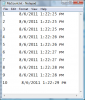
The problem (not a big problem) becomes what to do with the data. The data would look like this:
1 8/5/2011 10:58:17 AM
2 8/5/2011 10:59:07 AM
One solution might be to have the software open a text file in Notepad and just dump the data into the text file. The data needs to be logged somewhere. If the computer has Excel the data could be dumped into an Excel Workbook? The bottom line is the data needs to go somewhere.
Another option more off the shelf would be to buy an interface device like a USB DIO (Digital In Out) module and write the code for it. There are other options out there that include data logging software and hardware. Just a matter of your limitations.
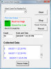
This is a link to a small simple software program that should do what you wish based on your post. Attached are a few screen shots of the program. The first image shows the graphical user interface and the second the resultant data file. The third image is a DB9 RS232 pin out.
The program downloads as a zip file. When you click the above link choose to download the file. Once downloaded right click the zip folder and choose extract. Open the extracted folder and double click Setup.exe to install the program.
When you run the program before clicking start choose the comm port from the drop down list, then click start. On my system it was COMM 3 as can be seen. When the program runs it will monitor the RS232 port pin #8. Every time pin 8 receives a low to high transition the pulse will increment the counter up one number as well as include the date & time stamp. This is visible in a few text boxes and the data is also dumped into a list box. The pulse signal to pin 8 can be anywhere between 5 and 12 volts. I used 5 volts in testing.
In addition to the list box the program automatically creates a small text file in the root of the C:\ drive named MyCount.txt. Clicking the Save button will transfer the contents of the list box on the form to the file, also, the file is automatically updated and saved every 10 seconds or so. The program could easily be expanded to monitor two more pins.
Anyway, if you can use it, there it is. A simple, very basic data logging program to monitor a single pin of the RS232 port.
Thanks everyone, ron your a legend thats exactly what i was thinking of, i tested it with just a 6v battery setup and it worked then i took that into excel and created a graph just like i wanted.
Now to work out the schematic to my needs.
Just a few questions.
Is the light sensor on the schematic a photo-sensor, i do have one from a old tv ir receiver, would that suit or is it like a sensor you would find in a day . night light?
Q2. What would be the configuration for the resistors to suit as i would want it to just trigger instant but believe the setup is for 10 second pulse.
Q3, it also said on the forum for the schematic that there is resistors for light filters, what would i need for a just a laser so the daylight / night light wouldn't effect it.
Q4. im thinking im correct in thinking the + of buzzer is pin8 and buzzer negatime is pin 5.
Thanks for the kudos but it really wasn't much to do. Believe me if I can code it then on a scale of 1 to 10 (10 being difficult) it would be a minus 3.
Had I known you had Excel I would have had the program programatically open an Excel workbook , populate a spreadsheet and run the graph. Hell I am pleased it does what you want as it is.
OK, for your application the linked to circuit is not a good choice. What I think you may want to do is read this link. A likely good choice for your photo detector circuit can be found in the link. Read down to the Photo Cell circuits. You want a variation of Circuit B. When the beam is broken you want the output of your detector circuit to swing high. Earlier in that link note Basic Comparator Operation. Pay attention to Circuit B. That circuit can easily be built around a LM311 single 8 pin package comparator. I would start looking in that direction for your photo sensor solution. I don't know your location but the needed parts could be bought at a local Radio Shack here in the US, but you may have to get a quad comparator (LM339) instead of the LM311 and only use one of the four comparators in the chip. They also sell bags of LDRs cheap and they are just a mix, one should work.
This site uses cookies to help personalise content, tailor your experience and to keep you logged in if you register.
By continuing to use this site, you are consenting to our use of cookies.

")