oneoldude
Member
This post replies to criticisms made by the self proclaimed audioguru (Uncle $crooge) re: my attempt to make the rightfully famous Linkwitz pre amp a bit more flexible by adding a switch to allow the MIC capsule to be biased either from ground to V+ or from ground to V- and to provide for a set-and-forget gain adjustment.
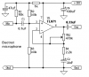
Here is the Linkwitz circuit. Scroll down to "Microphone"
http://www.linkwitzlab.com/sys_test.htm
Herr McDuck, you are at it again. All negativity, erroneous criticism and no real constructive help.
Only this time its worse. You intentionally failed to show my entire schematic in order to make an incorrect criticism. The entire schematic is the first post on the one page thread I point to below. If you look at the entire schematic you will see that the 10K resistor you claim is missing is next to the capsules in the top part of the schematic. But you chose not to include that part of the circuit and chose to make an invalid criticism again.
Here is the page:
http://www.htguide.com/forum/showthread.php?41165-Linkwitz-Pre-Amp-modification
Also, as usual, you do not do your homework. The first post in that one page thread was a schematic for discussion. It was not a final. Had you scanned through that one page thread you would have found the as-built schematic toward the bottom of the page. But you did not bother to even scan down one page and chose to give incomplete information to criticize, as usual.
In the as-built, the cap you circled in red (C2) does not even exist. The reason is mentioned on the as-built schematic. That should send you into convulsions. But Linkwitz apparently came to the same conclusion and did not use that coupling cap either. No cap at all will certainly widen the lower bandwidth in that portion of the circuit!
In any event you take the same position for C1. I just used what I have on hand and don't see a problem in having a very wide low end bandwidth for an instrument MIC. In Florida we don't have earthquakes and I don't measure during thunderstorms or even with air conditioning running, etc. This is something I discussed with you in another thread. Hmmmm Did you forget that?
Last, the motorboat filter you describe is not used by Linkwitz either. That is probably due to using a battery supply. It might be a good idea from a belt-and-suspenders point of view. But to do it would require a voltage divider and filter cap on the 10K MIC bias resistor. That lowers the voltage on the MIC and thereby reduces MIC linearity. It is an engineering compromise I do not know how to make or calculate. So for now, I think I will stick with a real pro, Siegfried Linkwitz, rather than incorrect, misleading, nebulous and unhelpful criticisms from you.
If you respond with anything other than a schematic of what you consider a high quality unbalanced circuit for ECM measurement MIC pre amp use that has not already been mentioned here and a description of how to make the engineering compromise entailed in the motorboat filter that you suggest, I will put you on my ignore list and not deal with your diatribes again.
Frank, sorry I misdescribed your filter. I was going from memory and got it wrong. I would still not use your filter for measurement use. I would shoot for a straight line to at least 20 Hz.
Thanks for putting up with this response guys, I think it will be the last re: Herr McDuck aka Uncle $crooge aka audioguru.