Thanks Guys,
Eric, that's a nice signal from the circuit, thanks for that.
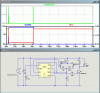
I noticed on the 12v power supply for the circuit, mine had tran 500u & yours has tran 0 20u 0 1u.
I am not sure what the difference is or how to set it differently?
Also the Load component, i had mine for a constant current draw 2A, the circuit that this circuit will trigger only draws power when triggered obviously, so how do i set the load characteristics to simulate this?
Thanks Again

")