Continue to Site

Welcome to our site!

Electro Tech is an online community (with over 170,000 members) who enjoy talking about and building electronic circuits, projects and gadgets. To participate you need to register. Registration is free. Click here to register now.

  • Welcome to our site! Electro Tech is an online community (with over 170,000 members) who enjoy talking about and building electronic circuits, projects and gadgets. To participate you need to register. Registration is free. Click here to register now.

ltspice simulation question

Status
Not open for further replies.

HeatherM

New Member
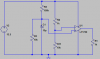
I am new to using LTspice and I have built a simple circuit to analyze the charging of a capacitor as input to a comparator.

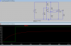
It seems as though the LTspice program only takes into the account the voltage after its charged. I re-simulated using an since wave and got the desired results.

This brings the question, how do I run a simulation where I can analyze the change in DC state of the cap charging?

Heather

Oh one more thing, I could have sword I saw a "tips for using LTspice" forum post here, but I have lost it or just plain seeing things?
 
Last edited:
I suggest that you try to post an image of your circuit within your message.

One way to do this is to look at the Tools list on the LT Spice screen. Try the copy bitmap to clipboard command, and then paste the result into the Windows Paint program.
When you get the circuit into Windows Paint, save to your desktop as a jpeg image. Next, use the paperclip icon on the advanced post message form to upload the jpeg image. .... The paperclip icon brings up the 'manage attachment' page, which shows the image forms that are allowed to be uploaded.

This may sound a little convoluted, and there may be a better way to do it ....It ought to work though.
 
Posting image maybe.

Was trying different values of resistor/cap combo, but couldn't get it to simulate so these are not the values im actually using.

Great I posted wrong image too :p
 
Last edited:
correct image
 

Attachments

  • test1.png
    test1.png
    6.7 KB · Views: 315
That image is fine...

I think that you can also save the LT Spice file, to a known location .... and load it as an attachment.
Have not actually tried it, but it ought to work.
This would allow simulation.
 
After you have run the simulation you should be able to click on the junction of R2,C1 to see the voltage from the start.

Mike.
 
Ok i resolved my issue. lol

I miss read the voltage divider of my actual circuit i had built. So now that
I changed it its, correct.

thank you
 

Attachments

  • corrected.png
    corrected.png
    21.8 KB · Views: 283
Regarding your initial question ....
It looks like the startup specification, under simulation commands, is necessary to get the correct transient graphs, otherwise LT Spice assumes that everything is steady-state.

.... Something having to do with initial conditions, apparently.
 
Last edited:
One item to investigate within your circuit would be the reference voltage value.
This would adjusted by changing the ratio of R1/R11, as shown in your circuit.

In some op-amps, as the magnitude of the input voltage value approaches the rail, or supply voltage, the op-amp will cease to function properly.

The idea would be to determine how close you could bring the negative input voltage terminal to the rail voltage, and still have the comparator switch correctly.
 
Status
Not open for further replies.

Latest threads

New Articles From Microcontroller Tips

Back
Top