Continue to Site

Welcome to our site!

Electro Tech is an online community (with over 170,000 members) who enjoy talking about and building electronic circuits, projects and gadgets. To participate you need to register. Registration is free. Click here to register now.

  • Welcome to our site! Electro Tech is an online community (with over 170,000 members) who enjoy talking about and building electronic circuits, projects and gadgets. To participate you need to register. Registration is free. Click here to register now.

LTspice Simulating a VCO oscillator

Status
Not open for further replies.

WagonWheel

New Member
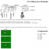
I have been trying to simulate a VCO for a CB radio on LTspice, but cannot get it to run. The ac analysis give me a peak at about 3.5 MHz but cannot get anything from the .trans. It is supposed to oscillate at 17.55 MHz. and is basically a LC circuit connected to Pins 1 and 2 of the chip TA7310P which are the base Pin1 and emitter Pin2 of an input transistor used as an oscillator. C5 on the spice circuit is meant to be a Varactor diode. V2 would normally be the dc control voltage. Would be grateful on any help on how to simulate this Please.
 

Attachments

  • VCO Block Jumbo Annotation 2019-12-23 233743.jpg
    VCO Block Jumbo Annotation 2019-12-23 233743.jpg
    109.8 KB · Views: 529
  • VCOforCB.asc
    1.7 KB · Views: 378
Thanks for your reply.........
Not sure what you mean. Do you mean dc bias on the transistor?. The transistor I added is to represent the transistor in the TA7301P chip. I added resistors but no difference. If I disconnect L1 and put a low freq signal on V2 I can see it work as emitter follower. also a high freq with L1 connected, but how does it work as an oscillator. It keeps asking for AC 1 when doing the ac response. There is only the 3 pins connected when it is connected in the CB ?. The CB is not working and I dont get the 17.55 MHz signal in the CB so assume the orig VCO block may be faulty ?, that is why I want to simulate the circuit for the New VCO Block befor I buy the parts??.
 
You'll need to find a data sheet for the TA7301 chip and add in the actual circuitry. Right now you have an incomplete circuit.
 
Yes, Ok, sorry about that. I have the datasheet, attached with this posting also I had the emitter resistor connected wrongly, so I have modified the Spice and attached it too. As far as I can see it is only connected to pins 1 and 2 with a DC control voltage to other. I still cannot get spice to show me it oscillating at 17.55 MHz.. C5 on the spice circuit is actually the varactor D1 on the datasheet for the vco. If I drive it with a voltage source I can see it operating as emitter folower but dont know how to set it up to oscillate on its own. Thanks for your help.
 

Attachments

  • TA7310P.pdf
    126.7 KB · Views: 444
  • Ver2_VCOforCB.asc
    2.5 KB · Views: 289
Try this. Disconnected the 'modulation' voltage source for testing. Changed base series resistor to 10K and added a 220 ohm at the emitter.
 

Attachments

  • Try_This.asc
    2.5 KB · Views: 351
Yes, that works, I read your reply on my phone first, didnt notice the attachment, so followed the text, Changed R1 to 10k and added 220 to R2 to make it 690, it gave me just short ringing oscillation for a few ms that died away. I changed R1 to 22k and it oscillates at about 16.7 MHz about 7 volt Pk to Pk. I then tried your suggestion and it works. R1 and R2 are to simulate the already resistors in the TA7310 chip. So it works, my initial problem was I had the emitter resistor connected wrongly and I was also trying the old VCO block on a breadboard as well and didnt notice it. Thanks for pointing me in the right direction. I will have to figure out the sums now to see why it works, I didnt have a simulator at my school??, The only thing I remember now about emitter follower circuits is the voltage gain is less then 1, and they have a high input impedance and a low output impedance..???
 
Where did you get the value of 100 ohms for the internal R1. I doubt it is that low. I just took a guess that it would be closer to 10K than 100 ohms. My added R4 would be external to the chip. I've found that adding that resistor to a Colpitts configuration always seem to improve circuit behavior.
 
The 100 ohm was probably not intended, I was trying all sorts to see if I could get it to work. I have since hooked up my old VCO block to a transistor on a breadboard as in the spice circuit and it oscillates at about 6.5 MHz ( should be 17.55 MHz ) but no change in frequency when the control voltage is varied, so maybe the varactor diode faulty.???. It is all potted so cant get at it. I will get the new bits and see if it works.
 
Yes, but let me see the old one working even varactor maybe faulty??.
Regards LTspice is there any forum that is dedicated to LTspice run by Analog/Linear systems.??? The old Yahoo groups.io forum has changed and seems to have a peculiar way of working????
 
Status
Not open for further replies.

Latest threads

New Articles From Microcontroller Tips

Back
Top