Continue to Site

Welcome to our site!

Electro Tech is an online community (with over 170,000 members) who enjoy talking about and building electronic circuits, projects and gadgets. To participate you need to register. Registration is free. Click here to register now.

  • Welcome to our site! Electro Tech is an online community (with over 170,000 members) who enjoy talking about and building electronic circuits, projects and gadgets. To participate you need to register. Registration is free. Click here to register now.

LTSpice, Isolated Circuit Simulation

Status
Not open for further replies.

ACharnley

Member
Hi,

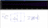
I have a 40V max AC circuit which is switching in a lot of MLCC's. At 50V these are very expensive and take up floorspace. I only need to switch them in up to 16V so I came up with the following to cut the power at a particular point then I can reduce the cost/size of these. The problem is without a resistor to ground the circuit will hang, but with it the graph is inaccurate as it's relative to ground. In other words, how to create a second ground and tell LTspice to use it for the isolated part of the circuit?

Regards, Andrew

PS) I haven't verified the op-amp yet, may have the +/- the wrong way round.
 

Attachments

  • Screenshot_2019-05-18_12-13-32.png
    Screenshot_2019-05-18_12-13-32.png
    40.6 KB · Views: 532
  • cap_tuning_proof.asc
    4.7 KB · Views: 241
The problem is without a resistor to ground the circuit will hang
Spice is happy if you use a ridiculously high value resistor to ground, e.g 1G, to maintain virtual isolation.
 
I tried the circuit without R1....it didn't hang.

It might be the opamp model you are using. I used an LM393 since you didn't include the opamp model.

eT
 
Spice can only have one ground reference.
But you can separate the circuits with a high value resistor as Alec suggested.
In the real world there's always some finite (albeit very large) resistance between isolated points anyway, unless it's floating in space.
 
I made a few spurious changes and got it working.

I hadn't seen this method of creating an isolated fet driver using a pwm and capacitors - it's working well!
 
you could also create a node with a label named "gnd2", connect it to gnd through a 1G resistor. instead of using a ground symbol, you would use a label flag (i usually use the "bidirectional" label). that way you actually have a "floating" ground. to connect other things, similar to what you did with "ac2" and "ac2x"
 
Status
Not open for further replies.

Latest threads

New Articles From Microcontroller Tips

Back
Top