Continue to Site

Welcome to our site!

Electro Tech is an online community (with over 170,000 members) who enjoy talking about and building electronic circuits, projects and gadgets. To participate you need to register. Registration is free. Click here to register now.

  • Welcome to our site! Electro Tech is an online community (with over 170,000 members) who enjoy talking about and building electronic circuits, projects and gadgets. To participate you need to register. Registration is free. Click here to register now.

LTspice Hartley oscillator wave packet / soliton is rectified on breadboard circuit

Status
Not open for further replies.
Hello,

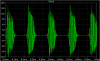
Here is a simple Hartley oscillator circuit in LTspice that when simulated results in a series of wave packets or "solitons."

The explanation seems clear: relaxation of capacitor C2 "modulates" the carrier frequency generated by the tank circuit formed by L1/L2/C1.

But when this circuit is realized on a breadboard the output is displayed on an oscilloscope, I get only the upper envelope. That is, the output is rectified.

Any ideas why this happens?

Thanks,
Electronaut
 

Attachments

  • HartleyOscillatorWavePacket1.asc
    1.9 KB · Views: 248
A real "tapped" inductor would have inductive coupling between L1 and L2.

Something like K1 L1 L2 0.7
 
Thanks, I tried adding mutual inductance like this, but it doesn't change the LTspice simulation much. I still get pulses that go positive and negative.

I'm not using an inductor coil, I'm using axial lead (color-coded) inductors like the ones in the attached image.
 

Attachments

  • InductorAxialLead.jpg
    InductorAxialLead.jpg
    8.3 KB · Views: 209
i added the following SPICE directive (not just text, it needs to be a SPICE directive) K1 L1 L2 0.9 and the circuit gives a continuous output waveform at 102khz.
 
Thanks, I tried adding mutual inductance like this, but it doesn't change the LTspice simulation much. I still get pulses that go positive and negative.

I'm not using an inductor coil, I'm using axial lead (color-coded) inductors like the ones in the attached image.

A true Hartley requires a tapped inductor with mutual inductance. If you built it with two isolated inductors, I dont know what it is; maybe it is a "motor-boating (blocking) oscillator"?
 
A true Hartley requires a tapped inductor with mutual inductance. If you built it with two isolated inductors, I dont know what it is; maybe it is a "motor-boating (blocking) oscillator"?
yeah, that's what it was doing when i ran the sim the first time. adding mutual inductance makes it work continuously, but he's not going to get mutual inductance by using those discrete chokes he posted a picture of... he needs to make two windings on a toroid core, or a single center tapped winding (which is the best solution).
 
as far as the "output appears to be rectified"... try adding a 100k load after the output cap.
 
To add a little context, this circuit is meant to simulate a flyback driver that contains no capacitor, yet shows ringing after every pulse, due to the junction capacitance of the MOSFET of about 1 nF.

Of course, I can use other parameter values and/or mutual inductance to get a result that looks more like a classical Harley oscillation, but that is not the objective, and it does not answer the question: why the physical circuit behaves so differently from the LTspice simulated one. The axial inductors should have minimal mutual inductance, so the LTspice schematic without mutual inductance should apply.

I suspect that the problem may be due to some limitation of the LTspice models used. The physical curcuit result looks like the LTspice simulated one, after it has passed through an AM demodulator. This may be due to the old 20 MHz analog scope that I am using. But the high frequency "carrier" should be about 1 MHz, well within the bandwidth of this scope.
 
when i ran the circuit as drawn, the high frequency component was 100khz.
as far as the appearance of the signal looking as if it was demodulated AM... are you measuring at the "out" terminal? what are you using for a scope probe? is it a standard 30pf/1Meg scope probe, or a BNC/PL-259 with coax cable and alligator clips? coax cable has a lot more capacitance than scope probe cable, and could be filtering out high frequency portions of the waveform (RG-58 cable is 31pf/foot, so a 6ft cable=186pf that's a lot of capacitance for a 1Meg input impedance)

are you sure you aren't using an "RF sniffer" probe? these usually have a pair of diodes and small capacitors inside them. there were many made commercially, and look very similar to regular scope probes. they were made for alignment of RF circuits. i've actually seen some scope probe sets that were marketed in the 1960s and 70s, where there was a regular x1/x10 probe, and a demodulator probe. a lot of "old" scopes might have these in the probe kit.
 
Thanks for the information. I'm using a Tektronix 2225 (50 MHz) scope with BNC probes with the alligator clip grounds (see image). I'm probing at point Out. If I probe before the output capacitor I get the same waveform with a level shift.

I did some radio frequency testing with this scope and do not remember seeing this kind of filtering.

If anybody tests the corresponding breadboard circuit and gets the same result that an LTspice simulation does, please post a picture!

I'll have to experiment with different probes. Thanks again.
 

Attachments

  • ScopeProbes.jpg
    ScopeProbes.jpg
    3.6 KB · Views: 193
can you post a picture of what you are seeing on the scope?
 
I'm attaching the LTspice trace and the Oscilloscope trace.
Scope probe used is the TP6100 set at X10, 18.5 pF, 10 MOhm, 2V/DIV, 5 us/DIV.
Things are a bit more complicated than I suggested earlier, because the period of the pulses in the LTspice trace is about 220 us, whereas the period of the pulses in the oscilloscope trace is only 20 us. Thus the Oscope trace is not just a filtered/smoothed version of the LTspice trace.

Perhaps the particular parameter values used results in a metastable state, or one that stresses the model assumptions made in LTspice.
 

Attachments

  • HartleyLTspiceTrace.png
    HartleyLTspiceTrace.png
    4.3 KB · Views: 197
  • HartleyOscopeTrace.JPG
    HartleyOscopeTrace.JPG
    1.5 MB · Views: 234
I'm attaching the LTspice trace and the Oscilloscope trace.
Scope probe used is the TP6100 set at X10, 18.5 pF, 10 MOhm, 2V/DIV, 5 us/DIV.
Things are a bit more complicated than I suggested earlier, because the period of the pulses in the LTspice trace is about 220 us, whereas the period of the pulses in the oscilloscope trace is only 20 us. Thus the Oscope trace is not just a filtered/smoothed version of the LTspice trace.

Perhaps the particular parameter values used results in a metastable state, or one that stresses the model assumptions made in LTspice.

that's because the physical circuit is only oscillating in one of the two modes that are present in the LTSpice sim of the circuit. the period is that of the high frequency mode of the circuit in LTspice, not the low frequency "blocking" mode. there's no rectification of the signal going on here, just that the operating point isn't quite right.
 
There does seem to be some instability here as well, in the sense that small changes to the parameter values can lead large changes in the result, perhaps due to the nonlinearities in the circuit that are not captured by the LTspice model. As you say, the operating point is not quite right. There has been some interesting work recently on the creation of true solitons in the context of electronics circuits: https://news.harvard.edu/gazette/story/2006/04/solitons-may-be-the-next-wave-in-electronic-circuits/
 
There does seem to be some instability here as well, in the sense that small changes to the parameter values can lead large changes in the result, perhaps due to the nonlinearities in the circuit that are not captured by the LTspice model. As you say, the operating point is not quite right. There has been some interesting work recently on the creation of true solitons in the context of electronics circuits: https://news.harvard.edu/gazette/story/2006/04/solitons-may-be-the-next-wave-in-electronic-circuits/
it could also be something like interelectrode capacitance in your breadboard, or lead inductance of the components. it's a bit of a misnomer to say this circuit is generating "solitons". from what i gather a soliton would be a wave propagating along a linear path on the surface of a semiconductor chip, similar to the way a waveguide works. the wavelength would be measured in micrometers. on the low frequency end of the spectrum, it could be argued that an ionospheric EMP wave propagating downward towards the surface of the earth might have characteristics of a soliton https://archive.org/details/HighAltitudeNuclearWeaponEffectsPartOnePhenomenology
 
Yes, the circuit here is a Hartley oscillator with a tank that is modulated by a relaxation loop (a blocking oscillator), whereas a soliton results when nonlinearities of the medium (waveguide, say) "cancel" dispersion that would naturally occur, resulting in a particle-like soliton that tends to retain its shape over time. Solitons have been studied extensively as solutions to a certain class of partial differential equations, and it is interesting to see them emerge in physically realizable circuits.
 
i suppose a pulse on an open-wire transmission line could have some similarities. the similarities would be more hypothetical than real, since what's propagating along the transmission line is an electromagnetic pulse, and not a group of photons. however, there are a lot of experiments you can carry out with an open-wire transmission line and a UHF oscillator or a pulse generator. there are a couple of advantages to using an open transmission line, first, it's open so you can make measurements anywhere on it's length, second, the wire is generally larger, so there's less loss from skin effect, and 3rd, the velocity factor is close to 99%, rather than 60% like most coax cable, so a wavelength of open wire line is almost the same as a wavelength in free space.
 
The main question raised in this thread is why the results obtained using the physical circuit are different from those obtained using LTspice. A little experimentation shows that the 1 nF capacitor is a critical component: the results are very sensitive to this capacitance, and the results obtained using the physical circuit depends on the type of capacitor (ceramic, film, etc.). In particular, when a Vishnay film capacitor (47 nF) is used the results obtained using the physical circuit are closer to those obtained using LTspice (with 1nF cap). I guess LTspice is not always a reliable guide for what to expect in a physical circuit.

My first experiments were done using ceramic caps, and the discrepancy between physical circuit and LTspice might be related to voltage and temperature dependence of capacitance, as explained here https://www.maximintegrated.com/en/app-notes/index.mvp/id/5527 .
 
Last edited:
there's another capacitance in the circuit that is dependent on applied voltage, and that's the B-C junction capacitance in the transistor, so the question would be how close is the transistor model to the actual transistor? you also have capacitor ESR, inductors with series resistance, stray capacitances and inductances in the physical assembly. i have actually not had a lot of trouble with LTSpice being incorrect by more than +/-10% on a lot of projects that i've worked on. that app note you linked is primarily about ceramic caps, and i've been seeing more info online like this, and have had the nagging question "why all of a sudden is this such a big problem?" well after looking at the app-note i think i understand it now. i grew up in a time when ceramic caps were the sizes of fingernails and larger. this effect of capacitance reduction with DC bias seems to be worst on the caps that are physically the smallest. most ceramics used in capacitors have piezoelectric properties (which is why coupling caps in amplifiers should never be ceramic). the smaller the cap is physically, the more influence the piezoelectric effect seems to have on the capacitance. what was a minor inconvenience in caps the size of a dime or quarter has become catastrophic on caps the size of an ant's butt. with film caps, it shouldn't be a problem as the dielectric is a different type of material, being a polymer instead of a crystalline oxide.
 
Status
Not open for further replies.

Latest threads

New Articles From Microcontroller Tips

Back
Top