Electro Tech is an online community (with over 170,000 members) who enjoy talking about and building electronic circuits, projects and gadgets. To participate you need to register. Registration is free. Click here to register now.
Welcome to our site! Electro Tech is an online community (with over 170,000 members) who enjoy talking about and building electronic circuits, projects and gadgets. To participate you need to register. Registration is free. Click here to register now.
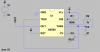
here is actual schematic I am wanting to simulate https://www.electro-tech-online.com/attachments/555-2-png.37477/
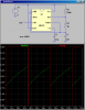
The device works great but would like to show a simulation if possible. Plan at this point is to just list all the different frequencies that the 555 outputs.
Am teaching a basic electronics merit badge class on Saturday. Did this last year and the scouts really enjoyed building this circuit. Pretty sure some parents didn't like it.
Built one for my grandson as well.
I DIYed the pc boards so total cost per completed unit was $3.57. Made 12 boards. In process of designing a new board using DIPTRACE instead of EXPRESSpcb.
Also building a board where it connected to the output - has 2-4017s , 10 LEDs. The first 4017 is a divider and second 4017 drives the LEDs "knight rider style"
As one presses keys the LEDs back n forth speed changes.
Young boys are fascinated by blinking LEDs and noise.
The schematic works rather well with LOTS of different "notes" depending on which two or more buttons are depressed.
This site uses cookies to help personalise content, tailor your experience and to keep you logged in if you register.
By continuing to use this site, you are consenting to our use of cookies.