Continue to Site

Welcome to our site!

Electro Tech is an online community (with over 170,000 members) who enjoy talking about and building electronic circuits, projects and gadgets. To participate you need to register. Registration is free. Click here to register now.

  • Welcome to our site! Electro Tech is an online community (with over 170,000 members) who enjoy talking about and building electronic circuits, projects and gadgets. To participate you need to register. Registration is free. Click here to register now.

LT spice OPAMP simulations

Emieldv

New Member
Hi,

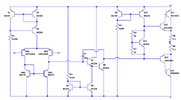
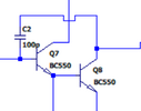
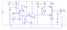
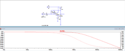
For a school project I had to design a opamp for audio amplification. I now would like to do an ac analysis on just the intermediate stage to see the gain and input impedance yet i am not sure how to simulate this. I remeber a TA talking about adding a feedback resistor that is 0.1 AC 1T but i cant seem to get it to work. The full circuit and the intermediate stage can be seen below. The Emitter current of Q7 is 1A and collector current of Q8 around 2A.
 

Attachments

  • Ampdesign2.PNG
    Ampdesign2.PNG
    82.7 KB · Views: 41
  • intermediate stage.PNG
    intermediate stage.PNG
    9 KB · Views: 37
  • AMPDONE2.PNG
    AMPDONE2.PNG
    91.6 KB · Views: 38
Likely you the circuit is not in its linear bias state.
Do an .op (DC operating point) simulation to see the bias conditions.

Post you .asc sim file.
 
1713660192365.png


Q4 Q6 form a current mirror, current thru Q4, is (V+ - Vbe) / R4

But Current thru Q6 may be scaled by emitter area, N of fingers......

That in turn is the emitter current of Q7, assuming beta Q8 very large,
hence its base current negligible.


Regards, Dana.
 
Thanks a lot for your replies but i dont think i made my question clear enough. The circuit works fine but i also need to make simulations of all the seperate stages. Just simulating the intermediate stage by itself doesnt really give good plots as there is no general feedback. I would like to find a way to measure the open loop gain the intermediate stage (So in this case the common emitter Q8) introduces and i would also like to measure the input impedance of the emitter follower Q7.
 
I would like to find a way to measure the open loop gain the intermediate stage (So in this case the common emitter Q8) introduces
Open the loop, measure the stage input and output voltages, do the sums (or use a behavioral voltage source to do the sums for you).
 
Just opening the loop and providing no feedback at all doesnt really seem to give usable results. Or am i doing it wrong?
1713700252754.png
1713700306849.png
1713700192246.png
 

Attachments

  • OpampV12Testmodel.asc
    6.1 KB · Views: 24
Hmm the gain being around -400mdb doesnt make much sense to me as the common emitter should introduce a lot of open loop gain. It seems to me that you took the output at the emiter of you Q4 but its supposed to be at the collector\
 
My approach would be to add a DC stabilising path around the whole opamp, then inject a signal and look at the output from each stage, compared to it's main or stage input.

eg. as a concept, a 100K from output to a cap to mid supply, then 100K from the cap to negative input.

Bias the positive input to mid supply with another 100K and capacitor couple the test signal to one of the inputs.

Add a cap to ground from the other input if needed & lower value resistors if the input currents cause too high an offset.
 
G is not affected by R1 for range of bias needed.

I do not sure that simulator, LT Spice, post your sim file and
let others here take a look at it.


Regards, Dana.
 
Last edited:

New Articles From Microcontroller Tips

Back
Top