Electro Tech is an online community (with over 170,000 members) who enjoy talking about and building electronic circuits, projects and gadgets. To participate you need to register. Registration is free. Click here to register now.
Welcome to our site! Electro Tech is an online community (with over 170,000 members) who enjoy talking about and building electronic circuits, projects and gadgets. To participate you need to register. Registration is free. Click here to register now.
LTSpice logic elements (inverters, buffers, gates, flops) are "idealized" (internal to LTSpice models of) logic elements, not like a specific logic family such as CMOS or TTL. They are optimized to simulate very fast, making simulations containing hundreds of them possible.
They operate on 1V.
They switch when an input crosses 0.5V.
They have an infinite input resistance ( ∞ fan-in).
They have an 1 Ω output impedance (almost ∞ fanout).
They have minimal switching delay, which can be modified on a per instance basis by attaching the Td=xxns attribute to the instance.
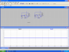
Look at the attached:
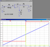
Note that the 10meg input resistor does not attenuate the input signal. Note that the gate switches as the input crosses 0.5V
Note that the output impedance at c and d is 1Ω, as shown when the gate is asked to drive a 10Ω resistor to ground or pulled up to 2V.
This site uses cookies to help personalise content, tailor your experience and to keep you logged in if you register.
By continuing to use this site, you are consenting to our use of cookies.