Electro Tech is an online community (with over 170,000 members) who enjoy talking about and building electronic circuits, projects and gadgets. To participate you need to register. Registration is free. Click here to register now.
Welcome to our site! Electro Tech is an online community (with over 170,000 members) who enjoy talking about and building electronic circuits, projects and gadgets. To participate you need to register. Registration is free. Click here to register now.
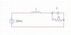
Well for example with R=2, C=10uf,L=1mH, and f=50Hz, we get:
Z=1.999921+0.3015934*j
which as i mentioned earlier this is a complex impedance.
But if you want to figure out the output with a current that is triangular, then we have to do a time domain analysis. But you also have to specify where your output is taken from...probably across the capacitor right?
Also, it might be better if you specify what the voltage is rather than the current. The voltage is probably pulsed right and so that makes it a little easier too. The current isnt really triangular in that case. It's close to a triangle, but not exactly.
So you next have to specify if you would rather analyze the voltage across the cap (the output presumably) with a pulsed input voltage, or you have to specify some other type of analysis but try to be specific so that we dont have to keep asking you more questions about it. The more specific you are the faster we can get you an answer
Also it might help if you specify some typical values for R, L, and C, and the voltage pulse amplitude.
Ok then maybe you were on the right track in the first place. Using the impedance you can calculate the peak AC current and then use that to estimate the max current.
I'll be back in a few minutes with more details...
LATER:
Since your output load is 12 ohms and the filter capacitance is so low in value (1uf) at 50 or 60Hz the resistive load dominates quite a bit, so the current through the resistor is 120/12=10 amps and the current through the cap is very little assuming 50 or 60Hz operation. That means the current through the inductor is also 10 amps, so the peak is about 14.1 amps. You should add a little more for safety anyway.
Be advised that with an inductor that large 310vdc may not be enough or might just barely supply enough current to drive the output voltage to 120v even at 50Hz. 315vdc would probably be the minimum requirement. Lowing the inductance relaxes this requirement and then you dont need so much overhead voltage.
This site uses cookies to help personalise content, tailor your experience and to keep you logged in if you register.
By continuing to use this site, you are consenting to our use of cookies.