Electro Tech is an online community (with over 170,000 members) who enjoy talking about and building electronic circuits, projects and gadgets. To participate you need to register. Registration is free. Click here to register now.
Welcome to our site! Electro Tech is an online community (with over 170,000 members) who enjoy talking about and building electronic circuits, projects and gadgets. To participate you need to register. Registration is free. Click here to register now.
A single resistor and a single capacitor makes a simple poor quality lowpass filter.
A inductor and capacitor makes a better one.
An inductor, a capacitor and a second inductor makes a much better one.
You can keep adding inductors and capacitors to make it better.
The inductor might be big, heavy, expensive and might pickup hum.
But an opamp can replace the inductor.
You can use a simple RC filter since the response time doesn't need to be that quick. Simply choose a very low cutoff frequency, such as 1Hz or less, and any 60Hz noise will be cut substantially.
That circuit is an adjustable amplifier, not an active filter. LM35 output is probably not going to go high enough to drive PIC input. You should amplify so that highest expected temperature reading is close to 5V and lowest is close to 0V - given that you are powering your PIC with +5V and ground. This will allow you to convert the voltage into temperature with a higher sensitivity.
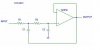
You can use the design below for a 50 Hz Butterworth (2nd Order, Unity Gain) Low Pass Filter with values (you may want to change frequency response to achieve more attenuation):
R1= 22 kΩ
R2= 22 kΩ
C1= 200 nF
C2= 100 nF
Suraj,
The LM35 in this application is used from +2Cdeg thru 100Cdeg
As the LM35 is 10mV/Cdeg, if you multiply the 10mV *100Cdeg *5 = 5Volts which is the Vmax the PIC adc accepts when using the internal +5Vref.
Without the OPA at 30Cdeg for example, the LM35 would only output 35 * 10mV = 0.35V.
Do you follow OK.?
What level of jitter do you have on the display and what resolution is shown on the display.. eg: 00.00Cdeg.. etc
Hi guys thanks for the replies now you have come upto the point.
My main problem is this.
I built a temperature display. It displays the temperature on three seven segments with a 0.5C accuracy (ex-26.5C will show on SSDs).I connect LM35 directly to PIC pin. References are Vdd & Vss.
When it’s changing its value between two points the display is getting jitter. Means it will show 26.5 & when reaches 27.0 it will shift between these two values 26.5, 27.0,26.5, 27.0……so the display is not stable always shift between two values.
This is the one I want to stop. I over sampled & averaged but still the problem is there.
What you could do is a running average which simulates a low-pass filter. For example you continually subtract the new temperature reading from the previous running average and add a fraction of that difference (with sign), say 1/4, to the running average (in a processor it's easy to divide a binary number by shifting the number to the right, 2 bits for divide by 4, for example). That way the running average can only change by a small amount each reading, minimizing the fluctuations
To vary the effective time constant of the filter you alter the amount you change the difference (divisor) before adding.
Is everything decoupled properly? You could be picking up enough noise from a power line or a signal line or from inside the chip itself to cause the jitter when the ADC is right at it's boundary for two values, very common. If you average enough samples it will go away, that noise can also be used to actually increase the resolution of your ADC readings. I've posted a link bellow to an AVR appnote that stands true for any ADC on any micro controller or system. If your sampling rate is flexible and you have enough memory you can increase precision quiet a bit.
I'm not subtracting, I continually sample & load the results into 16bit register.After taking 16 samples I divide it by 16 (right shifting 4 times).I have integer byte & a 4 bit fraction byte.
Again I have to divide my integer byte by 2 to display the actual temperature.This is the place I don't know how to add hysteresis.
How is your PIC setup? Can you post a schematic for it? To get full usable resolution out of your PIC's ADC isn't always easy. Also have you tested this on an o'scope (a sound card would work) to see if the noise is from the opamp or the sensor itself or from the PIC? If the actual voltage from your temperature sensor is clean completly read the ENTIRE ADC section of the PDF for your specific PIC and follow all it's precautions and suggestions for getting clean ADC readings. The single biggest thing you can do to increase stability of the ADC is to slow the conversion time down generally speaking the faster tha ADC clock the higher the noise. Depending on your PIC you may be able to bypass the analolg VREF all by itself, and there are grounding considerations as well.
This site uses cookies to help personalise content, tailor your experience and to keep you logged in if you register.
By continuing to use this site, you are consenting to our use of cookies.

")