Continue to Site

Welcome to our site!

Electro Tech is an online community (with over 170,000 members) who enjoy talking about and building electronic circuits, projects and gadgets. To participate you need to register. Registration is free. Click here to register now.

  • Welcome to our site! Electro Tech is an online community (with over 170,000 members) who enjoy talking about and building electronic circuits, projects and gadgets. To participate you need to register. Registration is free. Click here to register now.

Looking to use QTC Pills as a presure sensor for a USB dancemat project

Status
Not open for further replies.

Amphetamine

New Member
Hi, I'm looking to build an arcade style "DDR" dancemat for playing Stepmania on the pc. Instead of using mechanical contact for the sensor construction though I'm looking to use QTC Pills sandwiched between metal plates, for a sensor that's essentially got no moving parts.

I'll say at this point that I've only got a very limited knowledge of electronics, mostly picked up from when I worked at one of the maplin stores for a year. I have an understanding of logic and some soldering skills. I hope that they'll be enough to make this project work.

The basic construction of sensor would be 2 299x299mm metal plates with 12 QTC pills spaced out evenly between them. I'd also want to use the free space around the pills to apply 1mm thick high density, double sided self adhesive foam to keep the sensor held together and to stop the pills from moving around. The bottom plate would be screwed down to the mdf base, while the top plate would be screwed into the underside of an mdf tile, with an acrylic/polycarbonate tile screwed into the top of that.

The wiring from the 4 sensors will terminate at a 9 way D-Sub socket and then I'll use a standard RS232 cable to connect into an ABS plastic project box where the electronics will be housed. I'll be using the guts from an old USB gamepad as the interface (soldering straight onto that is a nice easy solution for me). Will also be soldering to some surface mount buttons to navigate the in-game menus.

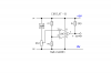
I want to be able to do a rough calibration of how much pressure is applied to the tile before it triggers the gamepad's ic to tell the pc that a the tile has been pressed. I think that what I need here would be a voltage comparator connected to the sensor and a screwthread style variable resistor (10MΩ Log?). This is of course where my limited knowledge of electronics runs out.

So, questions at this point are:

Is a voltage comparator the thing that I need? If so, any sugestions on a part number that's easy to get hold of?

Can anyone that's used QTC pills before see any issues with the way that I'm intending to use them?

Anything that I've overlooked?

Many thanks in advance.

-Jon
 
Ok, done a quick mock-up in SketchUp to illustrate what I'm building a bit better.

**broken link removed**


**broken link removed**


**broken link removed**

Hope that illustrates what I'm trying to achieve.
 
Last edited:
hi Jon,
You may know that the QPills have a resistance that varies with pressure.
They will also accept voltages over 5V.

I would suggest you build a single panel of QP's using the layout as in your pictures.

I suspect that the pressure on the QP will change the resistance enough, when say +5Vdc is applied will be enough to give about 5V change for the PIC's inputs without the use of comparators.

Do you have a ohm-meter or voltmeter.?

EDIT: a circuit a simple as this could work with the Q pills,

**broken link removed**
 

Attachments

  • esp06 Aug. 16.gif
    esp06 Aug. 16.gif
    2.7 KB · Views: 326
Last edited:
Got 3 or 4 of the cheap maplin multi-meters around the house/car/shed.

Looking at that diagram, It's running from 9v? I'd really like to run the entire thing from the USB's +5v, since I don't want to add an external power supply.

I thought about hooking the sensors directly to the gamepad's PIC at 1st, but 3 things bothered me: a) I don't know how much force is going to be required on the tile to trigger the PIC. b) I have a feeling that at low voltage the pic will strobe it's output, which is highly undesirable in this situation. c) I think that the resistance of the Qpills will change after a few months of use and I'd like to be able to compensate for that using trims on the control box.

I did a little search and found this diagram on a site:

**broken link removed**

The graph of circuit-b is exactly what I want to achieve, but where Ref-V is the output of an 18-turn cermet so I can calibrate the tiles to trigger on a very light touch. Some of the more advanced songs in dance games require 2 tiles to be pressed with the feet for a period of time and for a 3rd tile to be pressed with the hand, so getting the calibration right to do this is important for this project.

Unfortunately, I can't read circuits very well, so could you give me some advice about building cuitcuit-b in the above diagram (if you think it would be suitable for the task).

Thanks.
 
hi,
The common comparator I use is the LM393 its a dual device, that will work at +5V.

Datasheet here : www.datasheetarchive.com

Cct B would require a +V going pulse on the input to give +5V on the output.

RV pot circuit is drawn in a 'general' way, it would need to be changed slightly.

The junction of R1 and R2 [ and their values of course] set the +Vref to which the incoming +V pulse is compared.
When the +V input pulse is slighty greater than the Vref the output will goto +5V.

To design the RV would require some measurement of the voltage ranges you would expect from the QP pads.

EDIT: you would need to supply say +5V to the pills, which would have a series resistor connected.
 
Last edited:
hi,
Something like this.
I need to know the voltage outputs [ or resistance value] of the QP when pressed by the range of the forces applied during use.:)
 

Attachments

  • Image1.png
    Image1.png
    3.7 KB · Views: 259
Last edited:
Ok, I'll get my gear ordered up and do some tests to see what sort of numbers the Qpills are putting out under those conditions.

Also, just been having a closer inspection of the board from the usb gamepad... From the looks of it the buttons trigger the IC by grounding the legs, rather than by supplying the legs with 5v. Looks like this would need a modification to the design. I can upload an image of the board if it helps.

Thanks.

hi,
In that case circuit 'A' would be right one to use, leave off the 3K9 on the output.

When the input from the QP inverting input goes high, the output will be connected to 0V, low.

Upload your image.
 
hi,
Looking at the copper side of that board, can you confirm that all the push button switches have a common connection.

Also with the board plugged in, what voltage and polarity the sides of the push buttons that go to the ic pins, are at.

I would assume it would be that all the switches have a common 0V side and that the high side [ic pins] are at +3.3V or +5V.

Its important that we confirm that before making any connections to the board.
 
It's +5v on the pin side of the button contacts. All 4 of the contacts that I'm interested in using for the Qpill sensors definitly share a common ground.
 
It's +5v on the pin side of the button contacts. All 4 of the contacts that I'm interested in using for the Qpill sensors definitly share a common ground.
hi,
That sounds promising.:)

When you have built the first [ or prototype] panel section,
we need to know the range of resistance change you get when the panel is in normal use.

From these values we can determine the Vref etc... OK.
 
Last edited:
Maplin, but they are tiny! 3.6mm by 3.6mm by 1mm.
 
Thay're probably overypriced too, try shopping around.
 
In the US the distributor is CUI. No price listed.

I was suprised to not find them at SparkFun or Edmund Scientific. Not that either of these would have a great price but it would be nice to find them.

As Krumlink says Maplin has them
Code:
Bulk Prices Quantity Price including VAT :
1 £1.49
5 £1.34
10 £1.27
25 £1.19
100 £1.12
I think this is for a package of 4, none in stock.
 
Eric may have posted this before, but here is a good app note for the qtc pills.
**broken link removed**
 
Damn, I can't believe that maplin have sold out of QTC pills... They were showing 90 packs in stock just before the weekend. Doesn't look like I'll be getting my parts in time to build my project over the long weekend then :( Well, I can be getting on with the main construction while I wait I suppose.
 
How interesting I stumbled upon this thread. I too am attempting to construct a USB dancemat. I had never heard of QTC Pills; instead planning on using coiled surgical tubing under each pad connected to a small pressure transducer like this one. The idea was the tubing would be very quiet rather than two metal sheets smashing against each other. However, the QTC Pills might be a simpler solution if we can secure some.

The problem with the pressure transducer would be making sure the tubing doesn't blow apart from the sensor if someone really stomps the pad, or conversely, being sensitive enough if someone heels or toes a pad rather than a firm step.

Amphetamine. if you'd like we could collaborate on this project/design, it'd be nice to work with someone.
 
We talking Quantum Tunneling Compound Pills?? I am confused, never heard of a Q-Pill till now that is. Can anyone elaborate while I look it up..please.

Cheers,
-BaC
 
Status
Not open for further replies.

Latest threads

New Articles From Microcontroller Tips

Back
Top