Continue to Site

Welcome to our site!

Electro Tech is an online community (with over 170,000 members) who enjoy talking about and building electronic circuits, projects and gadgets. To participate you need to register. Registration is free. Click here to register now.

  • Welcome to our site! Electro Tech is an online community (with over 170,000 members) who enjoy talking about and building electronic circuits, projects and gadgets. To participate you need to register. Registration is free. Click here to register now.

Looking to illuminate the underside of paper guillotine

TheJay

Member
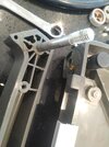
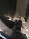
Hey everyone, it's really hard to get the alignment right with a guillotine and when I tried placing a torch underneath the paper, it made the job much easier as I had a visible line to guide me.

I need a bracket that can be mounted to the side of the guillotine allowing an LED strip to face upwards. Whilst looking at LED profiles, I came across this and it's a kit, kind of like I imagined when I started looking.

s448996296469462702_p17_i10_w640.jpeg

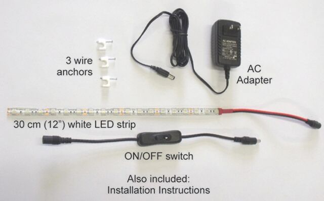
Does anyone know if all of these bits can be obtained individually from somewhere like eBay?

I'm ready to do some of it myself if necessary, as long as I can get the right components.

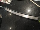
I saw a review saying the light wasn't bright enough, but that appears to be because the light was facing outwards rather than up and so the bracket I get needs to run the length of the blade, mounted to the base just under the lowest point the blade reaches when fully engaged.
 
You will find many LED light strips on ebay. This is one example.
This one runs from 12 volts DC so you should have no trouble finding a plug in power supply power supply. I have bought similar ones in the past and they consumed abou 60 watts for a 5 meter length.

Les.
 
It arrived. It came connected using a solderless connector a bit like this. I removed the strip and when I tried to put it back in and turn it on, nothing happens? What's wrong?
s-l500.jpg
 
It arrived. It came connected using a solderless connector a bit like this. I removed the strip and when I tried to put it back in and turn it on, nothing happens? What's wrong?
s-l500.jpg
It's probably not making contact?, did you try it before you removed it? - and why did you remove it?.
 
Are you sure that you did not reverse the polarity of the connections. If the strip is the same as the one I have brtween every group of 3 LEDs there are copper connection points (This is where you would cut the strip if you wanted shorter lengths.) Measure the voltage between the first of these connection points after the end where the power wires are soldered. You should measure about 12 volts and the polarity MUST match the marking on these connection points. If you have reversed the polarity you could have damaged some of the LEDs.

Les.
 
Thank you both for your replies. I wanted to see how it all worked, I've never seen those types of connectors before.

It was working before I removed it. There was only one end that the connector could be mounted on, so I didn't reverse the polarity (because it's the waterproof type and presumably the silicone has to be removed for it to make contact on the other end).

I can get it to work but I can't get it to work by clamping it in?

PX8flEJ.jpg

qw33CRY.jpg

The underside of the strip is covered in plastic, there's no obvious way the prongs will touch the conductors (in these photos they are touching from the end where I cut).
 
I think they look like some type of insulation displacement connector. (IDC) If you removed one and put it back in the same connector pads they may not make contact a second time. I have only ever soldered to the connection pads.

Les.
 
I think they look like some type of insulation displacement connector. (IDC) If you removed one and put it back in the same connector pads they may not make contact a second time. I have only ever soldered to the connection pads.

Les.
I planned to solder anyway, the connector was taking up too much space and making a mess. I've ordered DC-022 5.5x2.1mm DC Panel Mount Power Socket and Female to Male Plug CCTV DC Power Cable Extension Cord with a male and female end, so I can keep the two ends and use some of the length of cable to wire between the soldered LED pads and the female socket.

I'd be quite interested in having a mechanism that turns the power off when the blade is locked. There is a lever that stops it from being opened, when the lever is engaged. Any ideas?
 
A picture showing the lock mechanism would help. Possible solutions are a micro switch, a reed switch and magnet or an optical sensor, The optical sensor would take some current even when the lights are turned off. (About 10 to 20 mA.)

Les.
 
small micro switch such as this one would probably be the simplest solution. The lever on the micro switch could be operated by the hook part of the latch. (Post #11 picture 4)

Les.
 
Thanks Les, that sounds like a good option. So the switch would be located in the handle, that means routing a cable from the handle to the body of the guillotine. What's the best way to wire in a situation where a cable is going to be moving (because the pivot point is taken up by a bolt that holds the blade to the body of the tool)? I worry about cable fatigue.

Also, how would I know whether to choose 1A or 2A on the switch?
 
I don't know why that supplier lists items with different current ratings when they are the same physical size and both options are the same price. The 1A and 2A are the maximum rated current rating of the contacts. I don't think the LED strip will consume even 1 amp. (Unless it is a very large guillotine requiring a long LED stip ) The link was the first seller on ebay that I found with micro switches that look suitable. You will probably be able to find them cheaper and in smaller quantities than 10. From the pictures I can't visualise the construction of the guillotine so I can't suggest an alternative place to put the switch.

Les.

 
Look at the second photo, showing the underside of the guillotine with the latch and handle.

Could you drill a small hole through the end plate so a switch could be attached inside the front (in the top, as oriented in the photo) with the end of the operating lever through the end so it's operated by the blade, as that hits the fully down point?

It would not be operating directly from the lock, but it would hit the switch any time the blade is fully down, which it also is when locked.

A V3 style switch with a short lever could work there?
 
Yo2q9w7.jpg
kfa1PxF.jpg
3gx7yEq.jpg
mT7P2DH.jpg
VG9JSA7.jpg
PfvEsxK.jpg
 

Attachments

  • zoF4F9i.jpg
    zoF4F9i.jpg
    962.8 KB · Views: 106
  • gEDJknZ.jpg
    gEDJknZ.jpg
    1.2 MB · Views: 98
  • s0rPLli.jpg
    s0rPLli.jpg
    889.1 KB · Views: 106
  • QixrTXJ.jpg
    QixrTXJ.jpg
    755.6 KB · Views: 105
  • Z6XPL7F.jpg
    Z6XPL7F.jpg
    725.3 KB · Views: 112
  • L5RFZ5i.jpg
    L5RFZ5i.jpg
    1.1 MB · Views: 108
Thanks for your replies and apologies for not getting back sooner, I was waiting for parts to come from China. The V3 switch is too big for the space and I can't see a good place for a wire to transfer from the guillotine handle to the base.
 
I didn't mean to put the switch in the handle - I was thinking of it being inside the corner of the base in front of the latch, with the end of the switch actuating lever through a hole so it's pressed by the blade & operates the switch when the blade is fully down?
 
I was hoping to make it safer by making the light turn off only when the lock is engaged. I'm still hoping that there's a way.
 

Latest threads

New Articles From Microcontroller Tips

Back
Top