Continue to Site

Welcome to our site!

Electro Tech is an online community (with over 170,000 members) who enjoy talking about and building electronic circuits, projects and gadgets. To participate you need to register. Registration is free. Click here to register now.

  • Welcome to our site! Electro Tech is an online community (with over 170,000 members) who enjoy talking about and building electronic circuits, projects and gadgets. To participate you need to register. Registration is free. Click here to register now.

Looking for an H-bridge

Status
Not open for further replies.
It is a bit hard to describe the changes I mean. I added a schematic to show you what I mean on how you wire diagonal FETs to be controlled by the same signal in my previous post.

But now that it's there, do you see how you use the PWM to control it? And what I mean when I say one control signal makes the motor go forward and the other one makes the motor go reverse?
 
is this what you mean ?
 

Attachments

  • h-bridge 2 2 .PNG
    h-bridge 2 2 .PNG
    19.9 KB · Views: 425
Yes that's what I meant.

It makes no difference, but it might be easier if you move the inverters to the NMOS from the PMOS. Since the way I put the inverters (on the PMOS) it makes it so a HI is STOP and a LO is GO. If you changed it then a LO is STOP and a HI is GO which makes more sense.

Do you understand how the circuit works though? One pin will always have the FETs off, while you PWM the other pin to have it move with variable speed in a certain direction. And when you change directions, turn all the FETs off and wait a bit to make sure they are turned off and then apply the PWM for the new direction and you will never have shoot-through.
 
Last edited:
many thanks =)), hey i would use a 5V for the NPNs and i think the VGs is higher than 5V cuz this source is avaliable to me ... would be any problem ?
 
Vgs if a number of MOSFET gates, not NPNs. THe number you are interested in is the voltage drop across the NPN's base emitter diode. It's probably around 0.7V but it's in the datasheet.

So as long as your voltage is higher than 0.7V (to turn on the base-emitter diode), you size the resistor so that the extra voltage above 0.7V (ie. 5V-0.7V, if you use 5V) drives enough current into the base of the NPN. If the voltage is less than 0.7V, the you will not be able to turn on the base-emitter diode inside the NPN won't let any current flow into the base. THe calculation is the same as the one you use to size a resistor to control the current in an LED.
 
Last edited:
I mean 5V for the VCC for the NPNs so that the MOSFETs turns on using a 5V source ....

Rbase= 5-0.7/25ma (I source or sink from the inverter) = 172 ohms min resistor so i choosed 1kohms.
 
Your Rbase calculations is correct since your microcontroller (or inverter) outputs ~5V into the base of the NPN. But you are talking about Vb, not Vcc. You already connected each NPN to Vcc=12V through a resistor.

There are some things you should know. Vcc on your NMOS's NPN transistors must be a voltage that will turn on your NMOS when the gate is pulled high and not damage their gates, Your motor voltage must also be a voltage that is high enough so that your PMOS transistors can turn off when you pull their gate low. This places a minimum voltage that your bridge will work at (probably around 10V depending on your MOSFETs).

Also, your motor voltage can't be too high because of the PMOS transistors. When you pull their gate low, you can't exceed the maximum gate voltage or it will be damaged.

If you want to run your motor at lower than this voltage, things get tricky and more circuitry is needed. By far, the simplest thing to do is change your MOSFETs that need lower gate voltages to turn on and off.

I don't see any more problems in your circuit.
 
Last edited:
Im going to use a 5V for all the npns vcc cuz i've it instead of 12V, from the datasheet of the mosfets VGS max is 20V, why i cant then use a 5V !! ? and 24V for the upper mosfets ...
how do i calculate the Rc of the NPNs ? Rc= Vcc-Vce(sat)(0.4V)/150ma ?

from 2N2222 data sheet,VCEsat =400mv,at ic = 150ma, ib=15ma..

thanks really for being very helpfull ! wish you a good day
 
Last edited:
You can't use 5V because it is not high enough to turn on the NMOSs. If you go beyond 20V then you damage the NMOS. Maybe you can use a linear regulator or something but it might get too hot for Vcc.

The 24V for the upper MOSFETs might be a little bit too high (is it within the range of the maximum gate voltage for the PMOS?) Think about what Vgs is for the PMOS when you pull the gate low if your battery voltage is 24V. Vgs ~= 24V. Is it higher than the max gate voltage? It probably is by about 4V.

Rc has to be big enough so that your NPN won't burn out when it is on, but it has to be low enough to source enough current into the MOSFET gate to switch it quickly (to turn on the NMOS, or to turn off the PMOS). I don't know how much current this is, but my guess is that you want the current to be as high as possible without burning out the NPN. So if your NPN can handle 150mA, then size the resistor for 150mA:

Rc= Vcc-Vce(sat)(0.4V)/150ma
(just like you did)

I wouldn't worry about it too much- after all when you get the PCB you can always change the size of the resistor until you find one that works well. Other people on this forum know more about how to size pull-up resistors to drive MOSFET gates than I do. Maybe someone will tell us how to size it.
 
Last edited:
By the 24V i mean by The Vdrain of the PMOSs, and for the VGS for NMOSs i dont see why 5v cant turn it on ,the problem is in the datasheet it doesnt show the VGSth to know how much voltage needs to turn it on .. anyway im going to use 12V for it , but i need to know how to calculte the Rc of the NPNs
 
I edited my post (and what you did is what I would have done).

Can your PMOS handle a Vgs = 24V? Because that is what will appear when you turn the PMOS on (since you are pulling it's gate to ground, and it's source is connected to 24V). THis will damange the PMOS gate if it cannot handle 24V, which I don't think it can.

Rc for your PMOS will be different than for your NMOS since Vcc is different.

Vg = Vgth is NOT enough voltage to make your MOSFET conduct efficiently. It will be enough to just barely turn on your MOSFET. You need to have Vgs high enough to saturate your MOSFET. Look at Rds(on) in your MOSFET datasheets- it will tell you the resistance the MOSFET has when it saturates and the gate voltage you need to get it to saturate (all the way on the right column of the chart). It is 10V for your both your PMOS and NMOS. And the gates for your PMOS and NMOS can handle 20V. So you can't run your bridge off of >20V motor voltage right now, and your Vcc must be within 10V-20V for the NMOS's NPN transistors.

So the way your bridge is right now Vcc and the motor voltage can only be 10-20V. Anything higher than that will damage it (you can get around this if you use zener diodes and maybe a few more resistors in the right places to limit the gate voltage within operating limits).
 
Last edited:
I mean im going to use a seprate source for the NPNs Vcc which it will be 12V , and for the Vdrain for the P-MOSFETS will be 24V cuz its max VD is 100V
 
Then place a zener diode and resistor to limit the gate voltage on the PMOS gate. Because think about what happens when you turn on the PMOS- you are pulling the gate voltage to ground and the PMOS's source voltage is 24V. Your PMOS can only have a max of 20V between gate and source. So the max Vds is 100V, but the max Vgs is only 20V. You will damage it unless you do something about it.
 
Last edited:
Welcome to the world of motor drivers!

It's due to the way your gate drive works. You can spend quite a bit more money making very fancy gate drive circuits that float, and when you do that your Vdd and Vgs independent of each other and you can have a Vd =100V while your Vgs =15V.

One of the only reasons to use a PMOS for an H-bridge is that it is easier to switch on and off for the high-side than an NMOS. BUT if the motor voltage gets higher than the max gate volteage, then there is no point and that is the problem you are running into. You need extra drive circuitry, and in that case, you might as well use an NMOS since they are cheaper, faster, and more efficient than PMOS and need a fancy gate drive circuit anyways. So if you use these circuits then you should just change your PMOS to NMOS. You could also probably use MOSFETs with a Vds that is closer to your battery voltage (about 2x higher than your battery voltage to be safe) since they also have better performance than a high Vds MOSFET.

It's very easy to switch a low-side transistor on and off, but doing that on the high-side can be quite difficult. Here is a link to other methods that let you turn on and off a high-side MOSFET without needing isolators or floating supplies so they are cheaper:
**broken link removed**

So if you plan to use a motor voltage above 20V (15V to be safe) then you should change your to all power NMOS with more complex high-side gate drive circuit. It will be more expensive and complicated though than your circuit right now (mainly for the high-side gate drive). You might want to then try one of the circuits I posted in the link.
======================
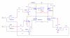
THis is the one I am working on right now (it's one half, there is a second identical half to it for the other side of the motor), for example. It uses floating supplies and the isolator can withstand 700V but drives the MOSFET gates with 15V, so if my MOSFETs have Vds max of 700V, my circuit can handle 700V.
It costs a lot of money though. You are probably better off using one the circuits in the link since yours is a low power, low speed circuit.

WHen it turns the top transistor off, it pulls the gate voltage it down to A, not down to ground since the voltage difference then would be much more than the MOSFET gate voltage can handle. Your circuit on the other hand just pulls the PMOS's gate voltage down to ground which is much cheaper and easier to do but it has it's limitations in that the motor voltage cannot be higher than max Vgs of the PMOS.
 

Attachments

  • Image1.gif
    Image1.gif
    28.3 KB · Views: 345
Last edited:
Status
Not open for further replies.

New Articles From Microcontroller Tips

Back
Top