Electro Tech is an online community (with over 170,000 members) who enjoy talking about and building electronic circuits, projects and gadgets. To participate you need to register. Registration is free. Click here to register now.
Welcome to our site! Electro Tech is an online community (with over 170,000 members) who enjoy talking about and building electronic circuits, projects and gadgets. To participate you need to register. Registration is free. Click here to register now.
I did check ebay and could find one, but it is very expensive at £6.25, I was hoping to find one on RS or farnell but not having much luck. Both of the aforementioned suppliers don't seem to do any in a T0202 package?
Good substitution would require knowing what the board does, and preferably a decent photo of the whole board.
Substituting just based on some datasheet specs is iffy. It's quite likely that once we know what it does then it might be perfectly happy with a device that has higher specs and will be more reliable. Also, do you know why the original part failed?
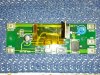
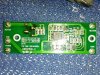
The board is from some GHD hair straighteners. I'm not 100% but I think this PCB senses current to regulate the heat, switched by the thyrister. Hope the photos help?
I repaired a temp controlled soldering iron that has very similar control electronics. The opamp IC on mine was Lm358 (your opamp is a 2903) and did the zero cross detect and temperature setpoint comparison.
It's a simple phase angle controller so the type of TRIAC or SCR does not matter that much. Mine was an AC triac. Yours seems be half-wave only, as it runs the power through big diode D9 before the thyristor.
You should have no problems using a thyristor of higher rated current and voltage, provided it has equally sensitive gate current Ilatch (as the opamp will have a limit to how much gate current it will provide).
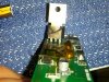
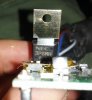
Also you didn't say as to the cause of failure, but that thyristor looks very much like it has seen massive current overload, ie a short circuit on the heater wires. It would be good insurance to put a fuse in series with the heater wires in case this might happen again.
I am just looking over the datasheets again (original part and the part I linked from RS) the gate current seems to be 0.2mA on the original part and 5uA on the RS part which is quite different?
the more I look at datasheets the more confused I'm getting
There should be a latching current listed or gate trigger current, normally it can be high as 30mA for a larger device and down to about 0.2mA or so for the smaller devices.
If your original part has Ilatch specced at 0.2mA you need a "sensitive gate SCR". It should be easy enough to find something. I would look for any larger part ie >=800v and >=5A that has a sensitive gate under 1mA. It may not need to be as low as 0.2mA.
Thanks very much Roman. Great help. Do you think I really need a part rated to 800v? Surely with a 240V supply the board will never have a voltage that large on it?
What was the original part's voltage spec? If you match that as a starting point it's likely to be ok.
I like lots of voltage overhead for safety, but it's probably not that critical. A 600v part would probably be ok on a 240v supply and a resistive load.
You still have not said what the original fault was that blew the first part?
the original part was 600v i think from the datasheet "The 3P4MH and 3P6MH are P-gate fully diffused mold
SCRs with an average on-current of 3 A. The repeat peak offvoltages
(and reverse voltages) are 400 V and 600 V."
Should be ok then? I'm not sure how the fault occurred to be honest? I guess it looks like a short?
It's probably ok, and worth a try. You never said what the wattage of the heating element was, but I guess it is FAR below 240v @ 2.5A that the C106M is specced at, that is 600W! Hair straightener clamps likely use something like a 50W or 60W element.
And as I said before if you can fit a fuse in series with the heating element, at the PCB end of the wires, that will protect the PCB if the heaters get some wiring short condition. A 240v 2.5A slow blow fuse should be fine.
That TIC106M part looks good! It's got the 0.2mA sensitive gate current of the 106 series but a larger package and 5A avg, 30A peak. Better than your original part, good work!
This site uses cookies to help personalise content, tailor your experience and to keep you logged in if you register.
By continuing to use this site, you are consenting to our use of cookies.

")