Continue to Site

Welcome to our site!

Electro Tech is an online community (with over 170,000 members) who enjoy talking about and building electronic circuits, projects and gadgets. To participate you need to register. Registration is free. Click here to register now.

  • Welcome to our site! Electro Tech is an online community (with over 170,000 members) who enjoy talking about and building electronic circuits, projects and gadgets. To participate you need to register. Registration is free. Click here to register now.

Long Range Infrared Emitter circuit & receiver

Status
Not open for further replies.

Team PSU

New Member
Hello everyone,
I ran across this site about a week ago when I was searching for long range IR emitter/receiver circuits. I am senior at Penn State University and we are doing a senior project where a portion of it requires an IR emission and reception. By long range I mean, we need to get at least 20 feet. I have been working and troubleshooting for some time now on this and can't seem to get it.

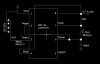
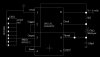
I am using a LM555CN chip set to output a 38kHz signal with a 50% duty cycle. I know this is the signal being output b/c I can see/measure it on the o-scope. The circuit can be seen in my attachment.

But here's where I run into problems. I am using left over components from a previous senior design project where another team has completed a similar task.
-I don't know the specs on the IR LEDS
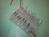
-I don't know the specs on the photoelectric receivers. But I do have their old setup (photoelectric receivers, resistors, and capacitors.)
-Their design report says they used a 38kHz signal with 50% duty cycle
-The receivers have the following marking:
19 235
V7000

So can anyone point me in the right direction where to go from here? I've hooked up their old unit and have a logic high, but when I place it in front of the IR LEDS, nothing happens.

Please advise (sorry if this seems like a scrambled message)
 

Attachments

  • ir emitter 2.JPG
    ir emitter 2.JPG
    34.6 KB · Views: 2,610
The four LEDs are wired in parallel which is bad.

The 1K current limit resistor between the LEDs and pin 3 of 555 timer is too large if the 555 timer is running from 5 volts, there will be only maybe 3 mA to the LEDs and the parallel configuration you have the LEDs are trying to share that.

Try 4 x 120 ohms from the 555 timer output, one to each LED.

How did the previous project have the LEDs connected?
 
Yes, don't wire LED's in parallel, it's a VERY bad idea.

Also you are driving them with almost no current - my IR PIC tutorials easily reach well over 10m, as do all IR remote controls.
 
The previous project (from '96) had very poor documentation and therefore no wiring diagram for the emitter circuit. And I will re-wire the LED's tomorrow when I get back to campus.

Anyone know anything about the receiver modules?

Thanks for the quick help.
 
You can drive LED's in parallel but only if each 'string' or individual LED has some series resistance added. Otherwise like Nigel said it's a horrible idea. Two diodes in parallel will never match their forward drop voltage so well that they share current equally. Best case scenario is one will carry more current than the other. Worst case, they'll oscillate.
 
You cannot make a circuit without datasheets for its parts.
An ordinary TV remote control has a range that is further than you want.
 
Ok, I have rewire the LEDs and they are working much better, emitting much more light. Additionally, we now have several of these units:
**broken link removed**
The IR receiver module on the board is a TSOP4838 and there is also a 34.6kohm resistor on the board.
The datasheet for the TSOP4838 module is here:
TSOP4838 Datasheet pdf - Photo Modules for PCM Remote Control Systems - Vishay

I need some assistance now in figuring out how to burst the signal of 38kHz. Do I simply need an additional 555 timer?

Please advise
 
EDIT - I got the receiver and emitter to communicate. But only up to about 5 feet. Now how can I pump more juice through the LEDs to extend the range?

I have the output pin of the 555 timer running into the blue power rail of a breadboard, and 8, 120 ohm resistors running to 8 individually wired LEDs. Will update the schematic soon.
 

Attachments

  • ir emitter 2.JPG
    ir emitter 2.JPG
    58 KB · Views: 1,320
Last edited:
5 feet? You're either massively under driving your LED or something is wrong. The carrier frequency might be miss matched and you're getting losses from the filter. A simple IR transmitter/receiver should easily be able to transmit any distance indoors that was line of site. Testing the LED is pretty simple, replace it with a white LED to see how bright it is, or use a digital camera to check the brightness of the transmitter relative to a TV remote.
 
You should be getting plenty of current to your diodes. I'm guessing your transmit frequency is just off. Do you have a scope you can use to determine the actual frequency you're outputting from the 555? If not just try trimming it with a variable resistor until you get better range. If you're actually using that many LED's you should be able to turn off any TV within line of site for at least 1000 feet.
 
What the heck is going on then? I know I am outputting a 38kHz signal (+/- 100-200 Hz both ways) with a 49.8% duty cycle.

The TSOP4838 is the IR receiver module being used. I have the ground to ground, + to + and signal on the oscope red, with the oscope black grounded...
 
How do you know? What did you use to actually measure the frequency of the carrier you're putting out? You only mentioned measuring at the receiver. Just because the receiver is getting a signal doesn't mean you're on frequency, the bandpass filters that IR receivers use are only first order filters generally so they'll still pick up off center carriers just at a dramatically decreased distance depending on the frequency variance. Blast enough IR power out close enough and they might even pick up unmodulated signals.
 
Last edited:
Your IR LEDs have a total current of 187mA. TV remote controls have a total current of 1A with a very short duty-cycle so the IR LEDs do not get too hot.

The IR receiver has AGC that reduces the gain if the 38kHz IR is continuous like interference from a compact fluorescent light bulb. It thinks your continuous 38kHz IR signal is interference so it reduces its gain.
Its datasheet lists the recommended number of pulses in each burst of "data" then the recommended duration for each pause between bursts of "data".
 
Ok. I'll run it down.

1. I have the exact schematic of the emitter hooked up to an o-scope. I have the red lead of the oscope to the signal wire leaving pin 3. I have the black oscope connected to ground (I have all grounds tied together).
2. I am reading frequency to be 37.98kHz and duty cycle of 49.8%
3. I have the Inex IR receiver module connected to a separate power supply and oscope. I have ground, positive 5V, and the signal connected to an oscope (with the ground connected too).
4. I can pick up the continuous 38kHz carrier frequency with the Inex board from close range (5 feet). I know this because when the receiver is not pointed towards the IR, there is a logic 1 on the oscope. When I am pointing it at the IR it becomes a logic 0 on the scope.
5. I increase the distance and am unable to pick it up at all.

So, if I can pick up the continuous signal at close range (without the bursts), why can't I pick up the continuous signal from a distance (without the bursts).

How can I increase the current leaving the 555?

EDIT - here is the emitter part of my circuit:
The red wire coming in at the bottom right hand corner of the picture is the signal wire. It enters in the - Blue power rail. Each resistor is 120 ohm and the red wire at upper left corner is the negative back to ground.
 

Attachments

  • IR emitter LEDs.jpg
    IR emitter LEDs.jpg
    54.1 KB · Views: 815
Last edited:
I explained before how the AGC (automatic-gain-control) in the IR receiver turns down the gain when it receives continuous 38kHz IR and the datasheet also explains it.

When the gain is turned down then it is not sensitive and has a short range.
It expects bursts of 38kHz pulses with a pause in between. The datasheet explains the number of pulses required to keep the gain at maximum for rar range.

TV remote controls use a transistor or a darlington transistor to provide 38kHz pulses with a current of up to 1A for far range.
 
Ok. I understand the concept behind bursting the 38kHz signal, and at this point, this is the only option I have left to pursue.

So now how do I obtain these bursts? Do I need to use another 555 timer?

I will do some searching, but would love suggestions and tips
 
Another 555 would work, but you'd have to adjust your receiver so that the missing gaps in the transmission wouldn't be interpreted as loss of signal. Maybe a simple low pass.
 
Guys, I can't figure this out...
I've been searching for how to burst the signal at a minimum of 10 cycles/burst with a gap time of 14 cycles.

Can somebody please show a schematic?

I also keep seeing something about placing a cap somewhere so the 555 can deliver a high amount of current?
 
Status
Not open for further replies.

Latest threads

New Articles From Microcontroller Tips

Back
Top