Continue to Site

Welcome to our site!

Electro Tech is an online community (with over 170,000 members) who enjoy talking about and building electronic circuits, projects and gadgets. To participate you need to register. Registration is free. Click here to register now.

  • Welcome to our site! Electro Tech is an online community (with over 170,000 members) who enjoy talking about and building electronic circuits, projects and gadgets. To participate you need to register. Registration is free. Click here to register now.

Logitech Z103 2.1 Stereo Audio Amplifier no Sound Ouput

Status
Not open for further replies.

iori3310

New Member
Hello.

I am posting here after a long time. Hoping to get some good suggestion on the issue. Let me come to the problem first.

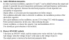
The audio amplifier PCB has no audio output (Left or Right). These are the current picture of the PCB from backside:
IMG_20191023_123309.jpg
Circuit After Replacement.jpg


The working diagram of the PCB is followed as this:
amp.png


The working diagram of the IC CD6282CS:
CD6282CS  Diagram.png


Pinout of the IC CD6282CS
CD6282CS Pinouts.png

Statistical chart of the IC CD6282CS:
gtasd.png


Current Voltage Reading on each pins of the IC CD6282CS:
ghasd.png


Some of the features of the PCB:
1) Single channel output jack for both Left and Right Speakers.
2) Direct power touch from 220V AC without any switch.
3) Has a volume controller but at the side of the Input wiring.
4) PCB is still strong enough for rework.
5) There is a single Z Diode, two Transistors and one UTC 4558 small circuit.
6) Checked both the speakers (left and right) with my laptop and android cellphone, they are working just fine.


Things I have done so far:
1) Changed both ICs as suspected for damaged and burnt of the previous ones.
2) Changed almost all the capacitors on the PCB, both Ceramic and Electrolyte.
3) Changed almost all the Resistors on the PCB.
4) Checked voltage output reading on the ICs (both UTC 4558 and CD6282) thoroughly again and again.
5) Checked incoming audio signals and it's working just fine.
6) Checked all the Capacitors for voltage output. They are just fine as well.


Some historical background:

First problem:
The left side speaker had less sound than the right side. After opening the sub-woofer, checked the PCB and found one bulged Capacitor attached with the left side speaker.

Solved the problem by replacing the cap.


Second problem:
I also checked with the test screwdriver thoroughly (that I shouldn't have) by touching the pins for voltage confirmation. It created some buzz sound and I stuck the screw driver for a long time. This damaged both the ICs CD6282.

I changed both the ICs but there was no sound output. From here, started my journey of solving this sound output problem.


Overall progress:
It's been 4 months straight, I am working on this PCB but still got no positive result on anything. I tried changing everything. But the result is still same. I will solve this problem no matter what. But I need help of the experts. And I am not giving up hope.

Assumption:
I am not an expert on electric components but I think it's the ICs that has audio output issue. Because I believe these circuits needs to be turned on somehow, which I don't know how, to have sound output. That's just my assumption based on the issue.

Suggestion:
I am expecting some real suggestion on solving the issue, because I got attached to my components and I believe I can fix it. So, I beg you, please help me out on this.

Waiting for your kind replies and suggestion. If you need more info just tell me what to do. I will describe more about the ICs or PCB.
With regards
Iori
 

Attachments

  • 1571814346553.png
    1571814346553.png
    19 KB · Views: 505
Usually you can get some Idea of where to look if you ask some basic questions like what happened that caused this etc... What has changed from when it worked to when it didn't. Always check the Power Supplies that the rail voltages are present. Could be a bad input connection or a relay that kills the signal not energized. Then there are the Output Transistors.
 
I also checked with the test screwdriver thoroughly (that I shouldn't have) by touching the pins for voltage confirmation.

Scary! What is a "test screwdriver?!?" If you shorted something out while "testing" your circuit, there might be several components that bought the farm.
 
I'd say the new ICs are faulty.

The output pins should be showing somewhere near half supply voltage if they were working properly.

The only other possibility is some kind of power save/shutdown circuit that's locking everything out, but the data sheet for those amp ICs does not show such a facility and the rest of the voltages do not look too unreasonable.
 
It helps a lot to have good meter probes sharp tips help probably time to get a good meter.
 
Hey guys,

I am showing you this photo of the front side of my PCB -
IMG_20191028_162052.jpg


Do you see the brownish and yellow colored Capacitors? I think some of these yellow color capacitors are bulged / swollen. What kind of capacitors are they? Can I replace them with the brown colored ones? Because these yellow colored capacitors are not available in my country. Both of these types of capacitors have numbers written on them. So, could they be the same?

It would help if you could guide me about this type of capacitor.

TIA.
Iori
 
Hey guys,

I am showing you this photo of the front side of my PCB -
View attachment 121372

Do you see the brownish and yellow colored Capacitors? I think some of these yellow color capacitors are bulged / swollen. What kind of capacitors are they? Can I replace them with the brown colored ones? Because these yellow colored capacitors are not available in my country. Both of these types of capacitors have numbers written on them. So, could they be the same?

None of those are swollen or bulging, and they are VERY unlikely to be faulty, they aren't the type of component that fails.

They are also commonplace, and will be available in your country if capacitors are? (they may not be yellow, most that I use are blue or brown) - disc ceramic and multilayer ceramic - but I wouldn't worry about them, as they aren't likely to be faulty anyway.
 
It still doesn't answer my question, if the yellow can be swapped with brown colored capacitors or not.

If you can find brown ones of the correct value, then no problem - but why do you think the colour makes any difference?.

As I mentioned, the multi-layer ceramics I use come in either blue or brown, depending on manufacturer, which depends on what's available when I order. Personally, by preference, I order the blue Murata ones, simply because they were the first I used, and it's 'prettier' than the brown.

But I'll repeat again, the chances of them been faulty are so near to zero as to not be worth considering. Replacing them is likely to cause far more problems than you already have.
 
Hi, thank you all for your suggestion.

I could not find the replacement of the multi layer ceramic capacitors as they are not available in our country Bangladesh. I am also unable to find the exact number of Ceramic Disc Capacitors for the replacement. Because they are also unavailable.

Anyway, today I checked the Voltage readings on the ICs' again and found this chart of voltages. I don't know what or how it happened but I am sure there are some changes in here.

1f.png


I have also found some Chinese documents on the ICs, I have translated and shown in here:

2d.png


Also some details on the each of the section of IC pin outs:

3d.png


4d.png


5d.png


6d.png


7d.png


These texts are all translated from Chinese document and using Google translator.

If anything is relevant here, please help me solve the issue. There are no sound output right now.

Waiting for your kind replies.

Thanks
Iori
 

Attachments

  • 6d.png
    6d.png
    61.5 KB · Views: 268
It looks like the IC's are faulty, more than anything else - it's a fairly obscure IC, how did you manage to source them? - presumably they came from China, so are probably faulty or fakes. The only two capacitors there which 'might' be in the ones you've been looking at are C6 and C7, which you could remove anyway and the amp should still work (they are to improve stability in to difficult loads, and should have a low value resistor in series anyway - similar to the speaker impedance).
 
Yes, these ICs' are made by China. And so was the first ones. They are available in our local market. Can you pinpoint which one is the faulty one? Should I replace both of them again?
 
There are no other sources of ICs available in our country. And also this CD6282CS is very much unpopular. And they also said, there are no ways to check ICs before buying. I already bought 10 of them. And yet, I am very much concerned. Although they are very cheap.
 
There are no other sources of ICs available in our country. And also this CD6282CS is very much unpopular. And they also said, there are no ways to check ICs before buying. I already bought 10 of them. And yet, I am very much concerned. Although they are very cheap.

If you've got a high power magnifier, or a microscope, try comparing the quality of the numbers printed on the chips with the originals, if you still have them?. A common technique in China is to clean the numbers off and reprint them with numbers for a different IC - so the chips 'might' be OK, but just the wrong chips.

I had some LM35's from China, ten of them - turned out NONE of them were LM35's - some were NPN transistors, some were FET's, some were thyristors. And as I'd bought them for stock over ayear previously, I couldn't even get my money back.
 
Hello, sorry for replying late.

I have changed both of the circuits again. But the voltage reading is same on both the ICs' from the above shared picture.

I am now going to search and find replacement for the Multi layer ceramic capacitors. Hope I will get a conclusion very soon.

Thanks for all the suggestion.
Iori
 
Hello, sorry for replying late.

I have changed both of the circuits again. But the voltage reading is same on both the ICs' from the above shared picture.

I am now going to search and find replacement for the Multi layer ceramic capacitors. Hope I will get a conclusion very soon.

Are they even in the power amplifier section? - the datasheet circuit you posted didn't show any (with the possible exception of the zobel capacitor, which you could remove and try without).
 
it looks like you definitely have a problem with IC2 since you have offset almost the full rail voltage on the output pins (p2 and p10). i would leave the ceramic capacitors alone, as they rarely, if ever fail... replacing those will be a waste of time and money.

the output pins (pins 2 and 10) should both have 6 or 7 volts on them if the chip is functioning ok. IC1 is probably also bad because it has pin 10 latched near the negative rail (or ground). there are two manufacturers of this IC in china Wuxi Youda electronics, and Shenzhenshi YONGFUKANG (i got this from ALLDATASHEET.com)
 
another possible cause of offset like that could be an open ground somewhere between the input stage ground and the power supply.
 
Hello.

I am posting here again. I don't seem find any hope relating to this PCB. It's very much sad to see these ICs' are the only ones that are available in my country. Anyway, for alternative, I would like to know if it's possible that now I have two speakers (left and right) attached with one 3.5mm jack for output can be used using a Sound card inside my PC. My PC has a PCI slot open.

Let me know if that's possible.

Thanks again.
Iori
 
Status
Not open for further replies.

Latest threads

New Articles From Microcontroller Tips

Back
Top