I got a ne 555p chip. I looked at the data sheet for this ne 555p chip.
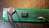
I can not figure out where the pin locations are.? The pic shows a half circle on the chip which tells me nothing helpful.
dropbox.com/s/fitler9s3jt0i64/NE555P.jpg?dl=0
As in where is pin #1 in this picture?
I can not figure out where the pin locations are.? The pic shows a half circle on the chip which tells me nothing helpful.
dropbox.com/s/fitler9s3jt0i64/NE555P.jpg?dl=0
As in where is pin #1 in this picture?