Continue to Site

Welcome to our site!

Electro Tech is an online community (with over 170,000 members) who enjoy talking about and building electronic circuits, projects and gadgets. To participate you need to register. Registration is free. Click here to register now.

  • Welcome to our site! Electro Tech is an online community (with over 170,000 members) who enjoy talking about and building electronic circuits, projects and gadgets. To participate you need to register. Registration is free. Click here to register now.

load cell amplification using AD620

Status
Not open for further replies.

Dhini05

New Member
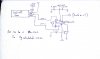
Hello friends, Iam currently doing a project on force measurement using shear type load cell.I am using one ton rated capacity load cell. The output of the load cell is about 0.9 mV.so I need to amplify it using AD620. The supply voltage for both is 15 voltsvolts.so kindly suggest me a circuit diagram for amplification from 0.9 volts to 3 or 4 volts so that I can fed to pick it microcontroller for convertion.
 
You would be better off running the whole circuit from a single 5v supply... There is a good example in the data sheet.

I use the INA125PA with two diodes as a reference.. My output to a pic is 1~4volts from a 0~1.6mV/V signal!
 
hi D,
Is your load cell rated at 0.9mV for 15v excitation.?
If yes, then when using a 5v excitation, the full scale output will only be 0.9mV * (5/15) ie: 0.3mV.

E
 
My load cells range of excitation is 9 to 15. V.the output(0.9mv) that I got is by just applying my hand force.it rated capacity voltage for one ton load cell is 45 mv(3mv*15=45mv)
 
hi.
OK, that makes more sense.
Running at a Vext of 5v will give 15mV for a 1 ton load.
If your PIC [mcu] is also powered by the same 5V supply, you could do as suggested and and amplify the 15mV up to 4V

Have you sketched out the circuit you could post.?

Eric
 
Hi sir ,I have inserted the circuit diagram. So please check it. Heartly thanks for your ccomments and replying me
 

Attachments

  • New Doc 7_1.jpg
    New Doc 7_1.jpg
    398.2 KB · Views: 1,297
No I had applied only 15 volts to it.as its an one tonn rated load cell , it requires excitation voltage of 9-15 volts
 
If I use the above circuit the out put comes of 11.35 V .its like the excitation voltage (15V)that I got.what is this problem.please give me some suggestions.
 
hi D,
With 15Vdc excitation, the unloaded load cell should have common mode output of +7.5v.
With the Vref pin at 0V, the Vout of the AD620 should be close to 0V.
If you set set the Gain, assuming a load cell output of 15mV at full load, to give a Vout max of 5V [ suitable for a PIC's analog input]
The Gain would be 5/0.015 = 333, a Rg of ~ 150 ohms would be required. [ I would suggest a 100R fixed and a 100R pot in series]

If you are concerned about over driving the PICs ADC input, ie: greater than 5V, use a series resistor and a 5.6v clamp zener diode on the Vout connection.

E

I would recommend a simple noise/RF filter between the load out and the input to the AD620.
Say a 10K in series with both the Inv and Non Inv inputs and a 10nF across the AD620 input pins,
 
hi D,
This is the circuit config I would recommend, the image and plot are from an LTSpice simulation.
The V2 source is the sim load cell signal over the expected range of 0mV thru 15mV [ if over driven the Vout is clamped at ~+5.4v]

With the weight of the Base that carries the load cell you find that there is Vout shift from zero due to the weight of the Base metalwork.
To null this out, you could introduce an opposite polarity low level signal at the AD620 input, using a high value resistor and trim pot, or
apply an offset voltage to the Vref pin, this should be from a low impedance source and trimmable.

If you want the maximum load of 1 Ton, set the Gain to give a Vout of 4.88V at 1 Ton. This will give 1000 counts from the ADC.
It makes the PIC's maths easier.

Eric
 

Attachments

  • A15.gif
    A15.gif
    35.6 KB · Views: 293
Thank you all for your wise advice. I got the output as there were some fault with my INA.I have changed it and got my put put
 
hi D,
That's good, lets know how it goes.
E
 
Yeah sure ,the output that I got is around 1 volt when I pressed it with my hands. Actually in my project a cylinders piston will hit the load cell. So its output will be good enough .its output is then given to ADC conversation and displayed in a LCD Display. That's all.
 
Hello frnds,the LCD output is fluctuating when no output is applied .can you give me some suggestions to nullify it. Its value is between 20-60.
 
hi,
For a check, short the load cell output connections together, use a very short link, keep the remainder of the circuit as normal.
Tell us what happens to the Vout fluctuation.

I assume that the leads from the load cell to the AD620 are screened.?
Is the load cell body connected to 0V.?
E
 
hello, frnds can any one suggest me a formula for converting the weight into force that needed to be displayed in lcd.
 
Status
Not open for further replies.

Latest threads

Back
Top