Electro Tech is an online community (with over 170,000 members) who enjoy talking about and building electronic circuits, projects and gadgets. To participate you need to register. Registration is free. Click here to register now.
Welcome to our site! Electro Tech is an online community (with over 170,000 members) who enjoy talking about and building electronic circuits, projects and gadgets. To participate you need to register. Registration is free. Click here to register now.
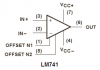
could i drive the base of a tip140 directly off of pin 6 on an lm741? or would i have to put another transister in between? if so what would i use? an 2n2222, and how would i bias it
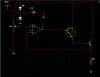
im useing a zener diode and capacitor as a voltage referance,i'm panning on drawing ten amps through 4 "to3"output transistors. it works without a load but when a load is put on it the voltage drops and the voltage at pin six on the op amp goes down to almost nothing. im going to try to post a schematic. i haven't doen it before so we will see what happens
There's nothing wrong with you connecting the op-amp output directly to the darlington base in THIS configuration. My guess is that the load causes the transistor emitter to drop to nearly zero volts, and the two bases will follow it down. This would happen if the load (R2) is extremely heavy. Also, have you checked Vcc to see if that drops also under heavy load?
D1 should be a resistor, not a diode. Either the zener or D1 will smoke as you've connected it here.
The zener diode is upside down with a voltage of only +0.7V.
The opamp doesn't have a power supply. It probably needs a negative supply in addition to a positive supply to allow low output voltages.
vcc stays nice and steady. i do have a resister between the two diodes i forgot to draw it. sorry. i did realize after studying the data sheet for the lm741 that the supply voltage is only good for 18 volts. i had 35 volts going to it. i added a lm7812 in the supply line to the op amp it worked for a while but i could only get about 15 volts out of the power supply and after a load it only puts out about 5 volts. i had this thing working when i built it a few years ago. i tested it but never realy used it because i didn't need that much current and i used my smaller store bought supply. i finaly needed the current and it quit working.
sorry i just drew it wrong. its been a while since i used the multisim and i was just trying to explain the layoput of the transistors. like i said it used to work fine. i could push 10 amps at about 25 volts into a modified toaster oven and the elements would glow. i let ir run for a while like that too to do a burn in test. i can jump 35 volts to the base of the output transistor, and the darlington and it will put out so i know the problem is before the darlington. i tested the voltage geting to the input of the opamp and it goes up and down with the pot and the invertiong input follows the output. the output of the amp just isn't correct. i don't know if its drawing too much current and cant keep up or what. now i did have a nec d381 in between the opamp and the darlington originally when it was working. i cn't find the spec sheet on it and don't remember what it is. i figured i should be able to bypass it. but mabey not? anyone know what the d381 is? my guess is a plain npn transistor but im not sure
Four output transistors in parallel with a 10A load each have a load of 2.5A. The minimum current gain at 2.5A for a 2N3055 power transistor is about 30 so the max current from the TIP140 is only 10A/30= 333mA. The minimum current gain of the TIP140 at 333mA is about 250 so the max output current from the 741 opamp is only 333mA/250= 1.3mA. The minimum output current from a 741 opamp is about 15mA so the circuit should work fine if all parts have minimum spec's. Replace the opamp.
i finally got it to work. the elements in my toaster oven are 2.3 ohms. it maxes out at 23.2 volts. i let it run maxed out for about twenty minutes. the heat sink was hardly warm. i had the oven on the floor and it was makeing my feet uncomfortable so i shut it off. then i went to resume my project that i should have been working on all day instead of this. i am running a fair sized stepper with a pic and four tip142s. i turned it on and it was drawing max current and the stepper wouldn't turn but kept shaking. then the smoke came out of my power supply. it was the op amp.what could be causing this. the power supply has the tip142s in between the stepper and itself so no transients should get through. is it a harmonic of the stepping frequncy destroying the op amp? any thoughts on this?
then the smoke came out of my power supply. it was the op amp.what could be causing this. the power supply has the tip142s in between the stepper and itself so no transients should get through.
If the transients are high enough they'll cause the junction of the tip142s to go into zener breakover and feed right into pin 2 of the poor little 741.... Put some clamping diodes accross the stepper coils.
A TL071 has the same pins layout and the same max output current of about 15mA as an741 opamp. But if the stepper motor makes unarrested voltage spikes then the TL071 will also be destroyed.
vcc stays nice and steady. i do have a resister between the two diodes i forgot to draw it. sorry. i did realize after studying the data sheet for the lm741 that the supply voltage is only good for 18 volts. i had 35 volts going to it.
could the voltage spikes get all the way back to the op amp though? it would have to get through the tip142s which have suppression diodes in them, then the output diodes of the power supply, the output transistors, the tip140 driving the output,the d381, then a 2n2222. i guess i could put my scope on the op amp and see what happens. i just don't want to keep destroying parts because it might take out something else next time.
This site uses cookies to help personalise content, tailor your experience and to keep you logged in if you register.
By continuing to use this site, you are consenting to our use of cookies.