Continue to Site

Welcome to our site!

Electro Tech is an online community (with over 170,000 members) who enjoy talking about and building electronic circuits, projects and gadgets. To participate you need to register. Registration is free. Click here to register now.

  • Welcome to our site! Electro Tech is an online community (with over 170,000 members) who enjoy talking about and building electronic circuits, projects and gadgets. To participate you need to register. Registration is free. Click here to register now.

LM358 Booster for Rail to Rail Output

Status
Not open for further replies.
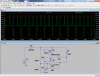
Mike, how is your circuit different from the one that MrAl originally posted? Other than some component value differences it would appear to be the same. Try adding a small extra load to the boosted output voltage and see if it still works.

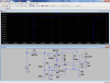
It would appear that whether the op amp only circuit works or not depends upon the models in Spice. Looks like someone will have to build the circuit for proof of concept.
 
I had previously added a secondary load, and that didn't stall it.

I didn't follow Mr Al's circuit when I first looked at it. Since it didn't work, I just went ahead and created my own as I went along.
The topology of the voltage doubler is the same except for the capacitance ratios.

One substantive difference is how the oscillator is biased. Mine comes from the boostapped voltage; Mr Al's comes from 5V.
 
Maybe your models have the same problem as mine. The 358 doesn't seem to get it's current from it's Vcc pin. The LT models seem ok.:facepalm:
 

Attachments

  • 358i.png
    358i.png
    89.4 KB · Views: 156
It is common for the VCC and GND pin current to not be molded (at all or correctly) in spice.
Some amps will run with out the VCC and GND connected. (only in Spice land, not in real life)
 
Hi again,

From my own study it seems to me that C2 (in either circuit without any transistors) only gets a small charge when the LM358 switches, but it's not enough to drive anything with. We need to be able to get at least 1ma i'd say, and that of course is with a real life circuit, and it would be nice to not have to use any additional drivers. Obviously this can be done with another IC chip in many many different ways, but i was looking at ways to do it without that. It may be impossible unless maybe we can generate a phase shift to charge C2 but that would cry for a sinewave oscillator. Interesting to think about though.
 
It is common for the VCC and GND pin current to not be molded (at all or correctly) in spice.
Some amps will run with out the VCC and GND connected. (only in Spice land, not in real life)

The LM358 model in the LTSpice sim I posted does correctly model the current flow from the Vcc pin to the Out pin when the OpAmp is sourcing current, and into the Out pin to the Vss pin when sinking current. It also does a credible job of modeling the magnitude of the LM358's source and sink current, including the Vol and Voh...

In the running sim, the peak charging current to my C2 is +-32mA (see Green trace on attached plot). That comes from the output pin of the LM358, so that same current alternatively flows into the Vcc pin or out the Vss pin. Note the dark Blue trace V(out). As you would expect, the LM358 will only pull within ~1.5V of Vcc when high, but pulls almost to Vss when low.

I also plot the current through C3 light Blue trace and V(bs) Red trace. Note that the current is very small because it is just acting as a bypass and the delta V is small too.
 

Attachments

  • BootstrappedLM358cur.jpg
    BootstrappedLM358cur.jpg
    391.8 KB · Views: 156
Last edited:
Hi Mike,

I dont see i(C3) all i see there is Vbs, Vout, and i(C2).
Where is i(C3) ?
 
Hi Mike,

I dont see i(C3) all i see there is Vbs, Vout, and i(C2).
Where is i(C3) ?

Sorry, I posted the wrong image. I fixed it. See if that answers your question...
 
Let me try it.
 

Attachments

  • Transformer.asc
    960 bytes · Views: 128
Hi Mike,

Very good :)

Sorry, I posted the wrong image. I fixed it. See if that answers your question...

i(C3) is the most important thing to look at. As we can now plainly see, we dont get the current we would expect in a normally operating voltage doubler. 100ua peak at 35 percent duty cycle means an average of 35ua, not nearly enough.
With a 33 percent duty cycle if we want to see 1ma of useful current for the other half section of the op amp (the goal) we'd need to see at least 3ma peak through C3.

I am happy to see people trying to improve this.

ronv:
Could you post your simulation results too?
 
Sure. I used the LT1013 as my 358 draws no current from the supply.
 

Attachments

  • boot.asc
    1.8 KB · Views: 141
  • boot.png
    boot.png
    107.1 KB · Views: 148
A take away from Carl's that gets the power from 5 volts. Also in the running for ugly schematic contest.:meh:
 

Attachments

  • chgpump.png
    chgpump.png
    90 KB · Views: 154
Deleted
 
Last edited:
...i(C3) is the most important thing to look at. As we can now plainly see, we dont get the current we would expect in a normally operating voltage doubler. 100ua peak at 35 percent duty cycle means an average of 35ua, not nearly enough.
With a 33 percent duty cycle if we want to see 1ma of useful current for the other half section of the op amp (the goal) we'd need to see at least 3ma peak through C3...

The average current in C3 is all about running the oscillator and biasing the opamp. It only takes 35uA to do that.
 
Hi,

ronv:
Yes that looks like the min requirement, at least one transistor. Maybe a mosfet would work nice too.

Mike:
Yes, with 35ua average current we can charge a cap up to 100 volts or more, but we can never draw 1ma from that. In fact we can never even draw 36ua from that for any reasonable length of time.
 
I had this idea several years ago and built a version to supply the V- for a quad amp. Al's and Mike's circuits don't work for the reason RonS has illustrated. Cruts' is better but has another problem: when the output of the amp goes above Vin, the base emitter junction will be forward biased and the charge pump cap will again be shorted out. To stop this you put a resistor in series with the base, as RonV has done. The other transistor , PNP in this case , can be replaced with a diode, cathode to amp output. The V- one I built and tested used a diode to charge up the cap when the output was high, and a PNP ( with base resistor ) to transfer charge to the resivoir cap when the output went low. The other sections were only minimally loaded so I don't know how much current this circuit supplied.
 
Last edited:
Status
Not open for further replies.

Latest threads

Back
Top