555
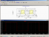
You need to make your schematic correct so we can tell which resistor is r1 and which is r2 for the calculator. Make your schematic look like the one in the picture and recalculate. I think you want the duty cycle to be close to 50% for best results.
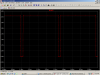
35 to 40 KHZ is ok.
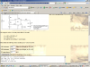
Maybe your circuit is different than your schematic?
You need to make your schematic correct so we can tell which resistor is r1 and which is r2 for the calculator. Make your schematic look like the one in the picture and recalculate. I think you want the duty cycle to be close to 50% for best results.
35 to 40 KHZ is ok.
Maybe your circuit is different than your schematic?
 My bad, I rushed etching and soldering the first design without having a thorough check.