Continue to Site

Welcome to our site!

Electro Tech is an online community (with over 170,000 members) who enjoy talking about and building electronic circuits, projects and gadgets. To participate you need to register. Registration is free. Click here to register now.

  • Welcome to our site! Electro Tech is an online community (with over 170,000 members) who enjoy talking about and building electronic circuits, projects and gadgets. To participate you need to register. Registration is free. Click here to register now.

LM324 with two 555 timer ICs

Status
Not open for further replies.

lloydi12345

Member
I would like to ask help again on how to solve this problem. I just lost my printed schematic. Can you help me troubleshoot this circuit again?

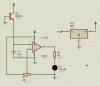
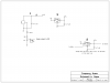
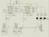
I placed the two of them in the same breadboard. The input (+) connected on the LM324 was an IR receiver module. I used a transistor symbol because I can't find one IR module on ISIS. Collector as 5v, base as Gnd and Emitter as output. The problem is the IR receiver receives a signal eventhough my IR LED is not present on the 2nd 555 timer circuit.

*I didn't used CV pin since I find it not really necessary so there is no C1 and C2 on the two 555 circuit.
 

Attachments

  • 38khz xmit.PNG
    38khz xmit.PNG
    56.9 KB · Views: 1,012
  • Capture1.JPG
    Capture1.JPG
    69.2 KB · Views: 661
Last edited:
I don't know your ultimate intentions but if you are in fact using an IR module like this one (IR Module) then you don't need the 324. Also, the output is normally high on those modules, only going low when a signal is present.
 
Yes. The LM324 is too slow to do anything. You are using it like a comparator but it is much slower than a comparator.
What is your circuit supposed to do? Re-create IR pulses? Are the 555s working at the correct frequencies?
 
I don't know your ultimate intentions but if you are in fact using an IR module like this one (IR Module) then you don't need the 324. Also, the output is normally high on those modules, only going low when a signal is present.

yes I'm using almost the same as this IR Module you've shown. I already made this one work before but I disassembled the components on the breadboard and I lost my schematic print out. I really wanted to use LM324 because it was already part of the design. I can add on the design, but I can't take LM324 off from the PCB design. I've been using LM324 on line follower's LDRs and LEDs. Now, I'm using it again on obstacle detections.
 
Last edited:
Yes. The LM324 is too slow to do anything. You are using it like a comparator but it is much slower than a comparator.
What is your circuit supposed to do? Re-create IR pulses? Are the 555s working at the correct frequencies?

What do you mean slow? Can you ellaborate it more?

The 1st 555 IC is to turn on and off the 2nd 555 IC's 38khz pulses so that the IR receiver will be able to recognize the IR LED. What the circuit should do is that when I place an obstacle in front, the light from the IR LED will reflect going to the IR receiver and the receiver will show a steady light on visible LED. There is no IR LED yet placed in the circuit and the IR receiver detects a signal. The LED indicator should be off since there is no IR light yet.
 
Last edited:
Since your questions are on many other websites then I won't waste any more time duplicating my answers. Good-bye.
 
Receiver

Hi Lloydi,
If I remember right you just wanted it to turn on and off. So a few things:
The detectors are very sensitive to noise close to their frequency so we need to make sure of a few things:
Do you have C5. It is important to eliminate noise from the 555's.
Lets not run the transmitter and receiver from the same power supply. So lets put the 555 to the 9 volts instead of the 5 volts. When you do this change R5 to 100 ohms to keep the LED current safe.
Add the little filter shown in the 5 volt line to the detector (100Ω & 4.7 ufd.).
Change the circuit as shown to the 324.
Add the 1ufd. at the 5 volt regulator.


LTX is right. the polarity is the opposite of what I have drawn
 

Attachments

  • 38.PNG
    38.PNG
    50.9 KB · Views: 260
Last edited:
Also, the output is normally high on those modules, only going low when a signal is present.
]There is no IR LED yet placed in the circuit and the IR receiver detects a signal. The LED indicator should be off since there is no IR light yet.
See above.


What else is on your PCB? If it's just a 324, lose it. The IR module can be directly connected to a microcontroller. Leave the space reserved for the 324 unoccupied if need be, or you could use it for something else. For line following or an LDR, it makes sense.
 
Correction

LTX is right. I have it backwards.
Let's try this.
Do all the noise stuff.
 

Attachments

  • 38.PNG
    38.PNG
    51.3 KB · Views: 238
See above.

What else is on your PCB? If it's just a 324, lose it. The IR module can be directly connected to a microcontroller. Leave the space reserved for the 324 unoccupied if need be, or you could use it for something else. For line following or an LDR, it makes sense.

Thank you for the reply.
I don't think the IR module can be directly connected to microcontroller because the signal is in doubt for the microcontroller to determine if it's high or low.
 
Last edited:
LTX is right. I have it backwards.
Let's try this.
Do all the noise stuff.

Thank you for the circuit.

Yes definitely there's C5 because it is the filter capacitor for the two 555 ICs.

I still don't get it when you say "backwards". Are you referring on the two 555 ICs circuit or LM324? Sorry for this silly question but I'm not really familiar with the software you're using. Uhm, are those figures that are 5 sided like pentagon are just labels? Or is it a label of another circuit which is not yet shown? Like for example "LED and Sensor". Is the connection point going to the LED or the circuit is named LED? Because there is a LED present and LED label beside it. I'm really confused although I admire the software because of the graphs it shows.

Other questions:
V2 is from a different power supply right?
Why is the indicator LED having the opposite polarity? I thought we're using the output of LM324 to light the indicator LED but you have shown me we're lighting it from 5v and the output acts as ground.
 
Last edited:
The first circuit I sent you for the 324 was backwards. The output from the IR sensor is minus when a signal is present.. The little labels serve 2 purposes:
1-so you can see where the waveform comes from. LED on the waveform comes from LED on the schematic.
2- Like in the case of +5 the program doesn't need another wire, just the lable to connect to +5.
The LED is in the opposite polarity so it will light when the signal is present, not when it is missing.
V2 is just there to simulate the output of the sensor.

Thanks for the explanation. I'll be downloading that software sometime when I'm not too busy anymore and study it.

I think I got it now how I made the circuits work before. The indicator LED lights when there's obstacle on it's path. I can now remember that the output pin of IR receiver module should be placed on (-) input of LM324 and the trimmer pot on (+). If I place the sensor's output on (+) the indicator LED lights steady and the trimmer pot on (-) then if there's an obstacle, it turns off. I think it's almost perfectly working. The only left problem is cleansing the scattered frequencies. Maybe you can add other recommendations ronv? Thanks again :D
 
Last edited:
Sensor

I'm not sure what your circuit looks like now.
Attached are some things you can do. You must do #1 then lets see what happens.
Please post your circuit again with the changes and results.
 

Attachments

  • sensor.PNG
    sensor.PNG
    71.5 KB · Views: 254
I'm not sure what your circuit looks like now.
Attached are some things you can do. You must do #1 then lets see what happens.
Please post your circuit again with the changes and results.

Oopsy, I think this is the reason why my two TSOP like IR receivers where destroyed. I forgot to look at the datasheet of TSOP18..SS3V and didn't place current limiting resistors. Uhm, why do we need 1N914 diode? Can you correct me with my understanding with a diode? I thought diodes where used to avoid voltages to come in to the cathode but allows voltage to pass through anode. It looks like the output can't come out from the sensor? Sorry I have a poor background in electronics.

EDIT: Is it fine I will leave CV pin of 555 IC blank? :D
 
Last edited:
The diode is there so that the negative pulses from the sensor will get through it to charge the capacitor but the positive pulses won't. So lets say the transmitter has been off for a long time. The capacitor will be charged up to 5 volts thru the 100K resistor. When you turn the transmitter on only the negative (0 volt) part of the pulse from the sensor will get thru to discharge the capacitor. Since the resistor that goes thru the diode is 10X smaller (10K) than the one that charges it back up to 5 volts the voltage on the capacitor will eventually go toward 0 volts. Your 324 can detect this voltage difference. When the transmitter turns off again and there are no negative pulses the capacitor will slowly return to 5 volts because of the 100k resistor.
It may work to leave the .01 ufd. off of the CV pin but sometimes it may not work. Almost any small value would be OK.

Oh, I didn't know that that can be another way of charging the cap. :D
Okay, I'll just place caps on CV pin. I'll just post problems if there would still be. I'll maybe first apply my own made circuit.
Really thanks a lot for the help!
 
Last edited:
Here is my current schematic. I solved the value of resistors using the 555 Timer Calculator in this website. Do you think I won't encounter any problem here? I'm designing now its PCB Layout. I used 556 instead of two 555.
 

Attachments

  • Capture.JPG
    Capture.JPG
    121.5 KB · Views: 343
Last edited:
Robot

There are a couple of problems:
R1, R2 and R3, R4 are not hooked up correctly.
The timing for the second timer is about 20khz not 38khz.
I think I misled you on the timing of the first timer with the simulation, but it should run at about 2KHZ.
Only one sensor has the 100 ohm resistor (R8)
Don't need 1 ufd. at the sensor output.
I'm still not sure how you will use the sensor outputs. Right now you will get a negative pulse out of the sensor at the same frequency as the first timer when it can see the led.
 

Attachments

  • x2.PNG
    x2.PNG
    55.2 KB · Views: 231
There are a couple of problems:
R1, R2 and R3, R4 are not hooked up correctly.
The timing for the second timer is about 20khz not 38khz.
I think I misled you on the timing of the first timer with the simulation, but it should run at about 2KHZ.
Only one sensor has the 100 ohm resistor (R8)
Don't need 1 ufd. at the sensor output.
I'm still not sure how you will use the sensor outputs. Right now you will get a negative pulse out of the sensor at the same frequency as the first timer when it can see the led.

It's fine, you didn't really misled me alot. Uhm, let me show you the approximate calculations where I based the values of resistors and capacitors. They are from the software 555 Timer Calculator on this site.

556A results to 780 Hz
556B results to 38.5 KHz

So do you think the frequency 780 is already good or should I change it to have exact frequency of 2khz? Do I really have to make the 2nd timer do 38Khz exact? or it can be like 35-40 Khz?

About the sensors, yes their output is 0 from LM324 if they can detect signals from the emitter and they are steady 1 if there's no signal detected. BTW, the sensors were not all the same because I just got them from a TV junkshop and the IR receiver modules are not sold on our place. I just had trial and error on how to make them work so they have different pin assignments. Luckily, they responded pretty nice on the emitter I've made based from your schematic. :D

If I remove 1uF on the sensor's output, the signal output doesn't become steady. What I mean is that, the output from LM324 ( (+)input connected to sensor's output and (-) to 10k trimmer) using an indicator visible LED, it blinks on a different pattern. Sometimes the blinking rate is fast sometimes not. If I place 1uF, then the result is steady on or steady off. Will it be wrong if I'll place alot of capacitors? Do they have bad effects on a circuit?

Right now all of them are working and no problems are yet encountered. Maybe you can help me to avoid future problems.

Thank You ronv :)
 

Attachments

  • Capture.JPG
    Capture.JPG
    68.1 KB · Views: 208
  • Capture1.JPG
    Capture1.JPG
    70.1 KB · Views: 206
Last edited:
Status
Not open for further replies.

Latest threads

New Articles From Microcontroller Tips

Back
Top